
On this page
Map the wanted and unwanted signals
Defense communication filter design should start with the signal environment. Map wanted channels, adjacent signals, blockers, harmonics, spurious energy, receiver sensitivity, transmitter power, duty condition, and the platform path. Then define passband, stopband, transition, isolation, impedance, thermal, packaging, and service requirements.
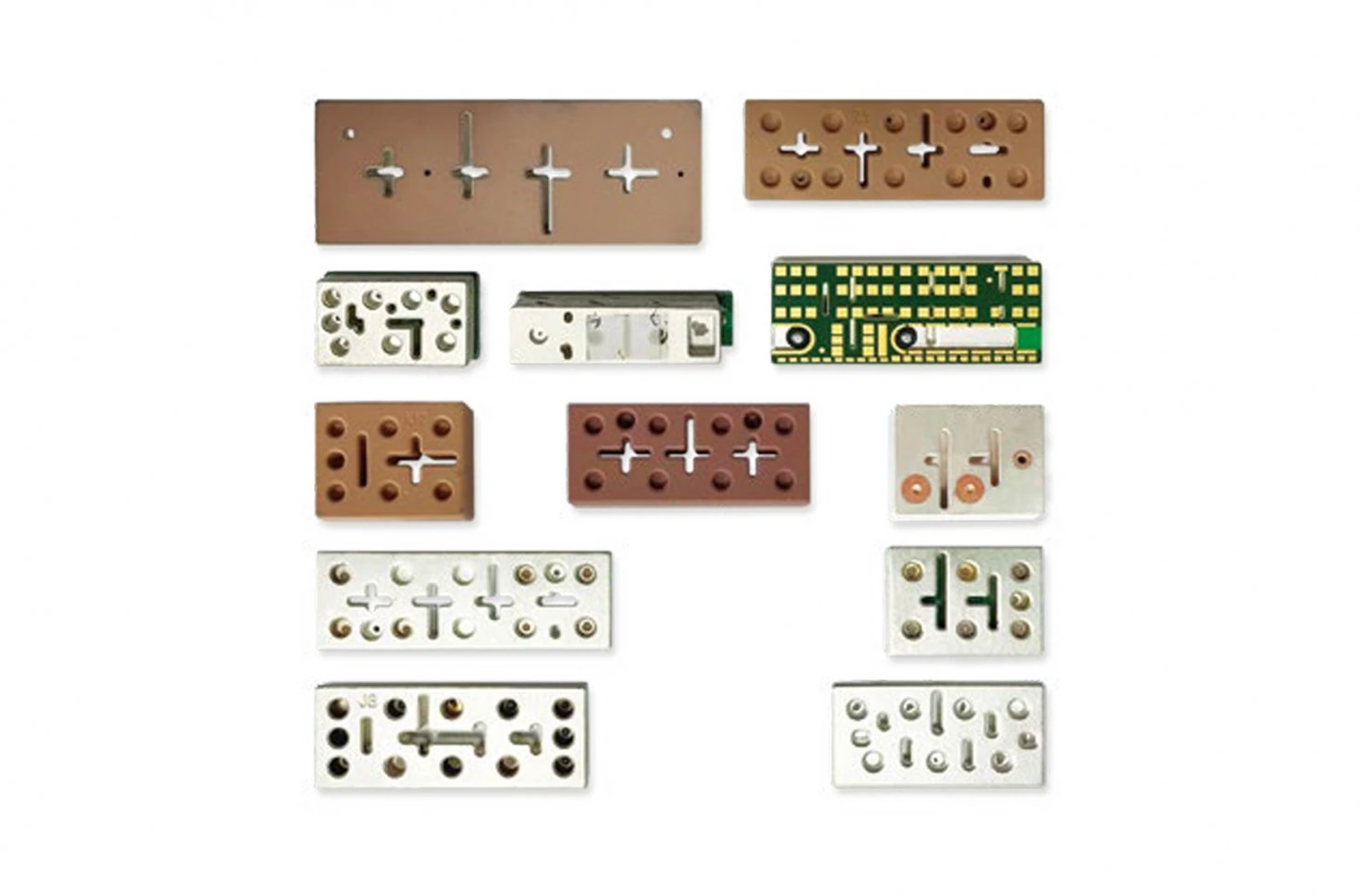
Keep the system boundary explicit. A filter at an antenna port, receiver front end, transmitter output, or shared network faces different power, linearity, and termination conditions. The same response target can mean different risk in each location.
Separate blockers and harmonics
List the unwanted signals by source and consequence. A blocker may require rejection near a wanted channel; a harmonic may require attenuation farther from the passband; an adjacent transmitter may require isolation and linearity under a high-power condition. Do not combine these into one generic “interference” line.
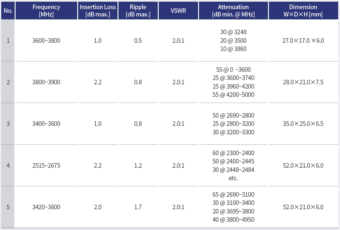
| Signal issue | Design question | Evidence to plan |
|---|---|---|
| Adjacent blocker | how much rejection at what offset? | stopband or isolation trace |
| Harmonic | which order and power condition? | harmonic attenuation measurement |
| Shared path | what does the other branch see? | port isolation and termination test |
| Thermal state | does loss create a relevant temperature rise? | power and temperature condition |
The filter should be evaluated with the source, load, cable, and enclosure assumptions that define the real path.
Consider power and linearity
Specify average and peak power, duty cycle, crest factor where relevant, expected mismatch, and thermal path. A low-level S-parameter sweep does not prove behavior under a transmitter condition. If compression, intermodulation, or other linearity concern matters, make it a separate acceptance item with its own fixture and instrumentation.
Review connector, housing, heat path, fasteners, and nearby materials as part of the design. A filter that is electrically suitable on a bench may need a different package or mounting boundary in the communication platform.
Design isolation into the topology
Shared feeds, duplexed radios, and multi-band paths require more than a single passband plot. Draw the ports, branch terminations, common path, antenna, switch, cable, and receiver or transmitter interfaces. Identify where energy should pass and where it must be contained.
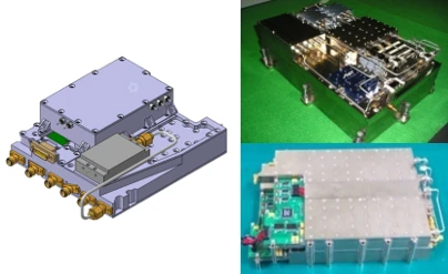
Isolation is meaningful only with the branch and termination condition stated. If an inactive port is open, mismatched, or connected to another active chain, the result can change. Record the operational termination in the measurement plan and the released configuration.
Plan thermal and environmental integration
Define the expected temperature range, heat path, enclosure, sealing, vibration, service access, and platform mounting. If environmental exposure matters, connect it to a tailored sequence and a pre-test/post-test RF comparison. Do not describe the filter as qualified or certified without the authoritative project evidence that supports that statement.
Keysight’s filter measurement overview identifies dynamic range, S-parameters, insertion loss, return loss, passband flatness, and group delay as relevant capabilities for frequency-selective devices. Use the measures that support the system decision, and state the sweep, power, temperature, and reference plane.
Verify the complete assembly
Create a production-intent verification plan with article revision, drawing, materials, connector, cable, fixture, calibration, frequency sweep, power, temperature, and acceptance criteria. Rohde & Schwarz describes fixture characterization and de-embedding for removing lead-in and lead-out effects from DUT measurements; document the setup when that method is used.
Compare the released assembly with the requirement map. Preserve traces, data files, deviations, and disposition. If a housing, connector, material, or process changes, decide whether the RF, thermal, isolation, or linearity evidence must repeat.
For a filter design review with MAC technologies Inc., provide the signal map, power and duty conditions, platform interfaces, port topology, packaging constraints, and acceptance plan.
RF technology insights gives related context, while RF antenna and component resources and the applications hub organize further review.
Keep the design decision traceable
Review the complete signal path against the RF, thermal and isolation requirements. A change in spectrum, power, platform or port topology should trigger a review of the affected tests and release records.
Use a requirements matrix that links each signal condition to a design feature and a verification method. For example, a blocker can map to a stopband or isolation limit, a harmonic to an attenuation point, a high-power condition to a thermal or linearity test, and a platform constraint to a packaging inspection. Keep the matrix revision-controlled so a new waveform, port, or enclosure does not silently invalidate the filter evidence.
Assign an owner to each open issue and record the evidence needed to close it. RF, mechanical and system reviewers should resolve related limits together when a change affects more than one discipline.
References
Keysight — Scalar Network Analyzer: Migrating from Scalar to Vector Network Analyzer Systems, “Filters and Frequency Selective Devices,” pp. 13–15.
Accurate Test Fixture Characterization and De-embedding
https://www.keysight.com/ie/en/assets/7018-02338/technical-overviews/5990-4798.pdf