
Evaluate a military RF filter manufacturer against the signal path and operating environment. Specify passband, stopband, loss, matching, rejection, power, interfaces, temperature, and mechanical requirements with measurable acceptance limits. Request evidence for the proposed filter and platform conditions.
The procurement record should separate three questions: what the filter must do electrically, what it must survive mechanically and environmentally, and what evidence the supplier must deliver. A meaningful supplier comparison should therefore connect every electrical, mechanical, and environmental requirement to attributable evidence and a defined acceptance method.
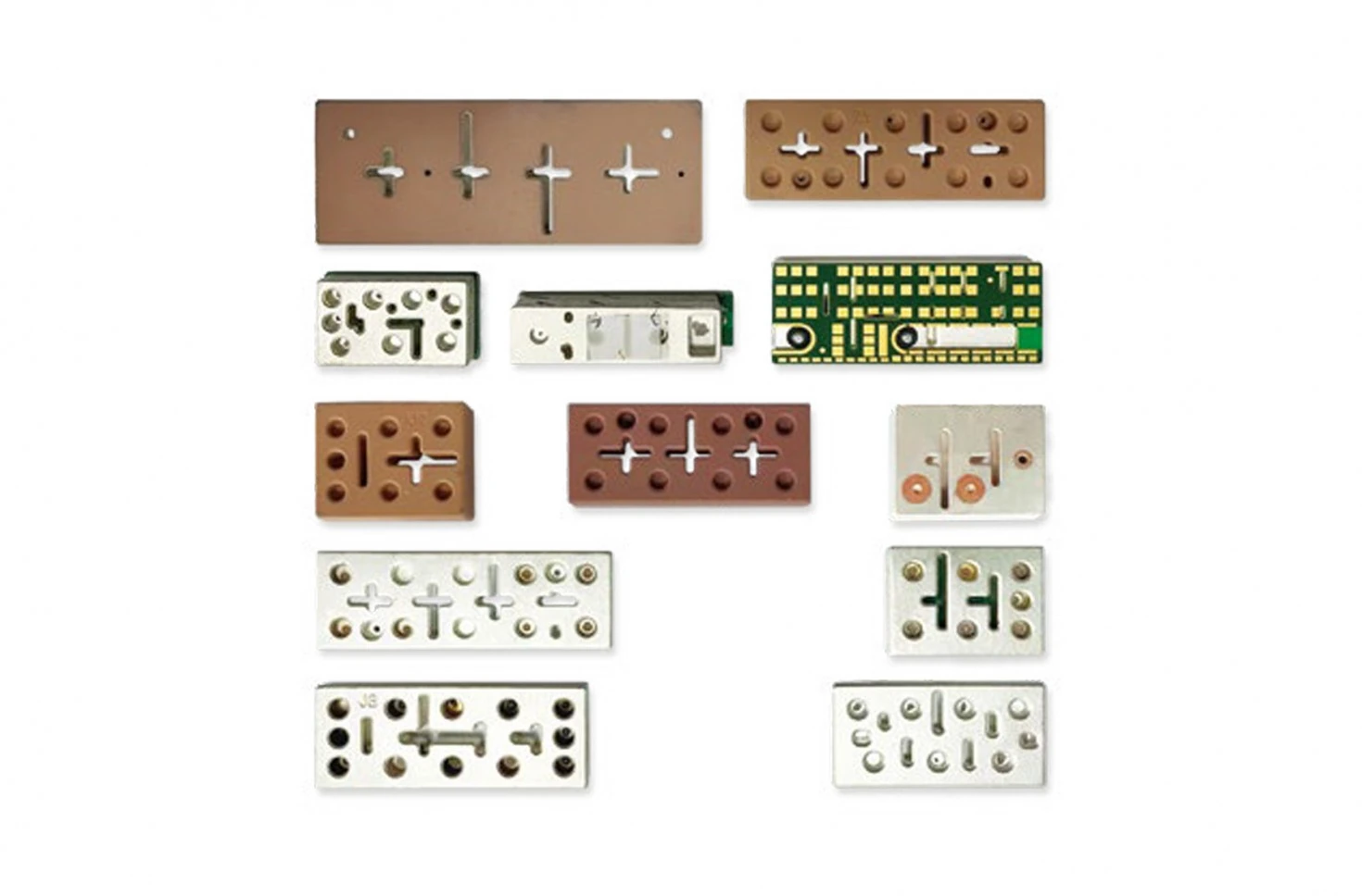
What unwanted-signal problem must the filter solve?
Define the wanted channels, nearby transmitters, harmonics, blockers, receiver limits, and operating modes before choosing a topology. A band-pass, low-pass, high-pass, band-stop, diplexer, or multiplexer is useful only when its transition regions and terminations fit the system. Include source and load impedance, port count, signal direction, simultaneous transmit conditions, and allowable interaction with adjacent paths.
The initial requirement table should cover:
passband limits and maximum insertion loss
stopband regions and minimum rejection
return loss or VSWR at every relevant port
isolation between diplexer or multiplexer paths
group delay or phase requirements where waveform integrity matters
continuous and peak RF power, duty cycle, and mismatch conditions
connector, package, mounting, grounding, and thermal interfaces
Topology follows the signal-path requirement
A band-pass filter preserves a defined channel while rejecting frequencies above and below it. A low-pass or high-pass filter preserves one side of a cutoff and rejects the other, while a band-stop filter targets an unwanted region within a broader useful spectrum. A diplexer separates or combines two frequency paths at a shared port, and a multiplexer extends that function to additional paths. The correct choice follows the wanted and unwanted signal plan, transition regions, port terminations, power, packaging, and isolation requirements; the topology name alone does not establish suitability.
| Requirement Area | Buyer Must Define | Evidence to Request |
|---|---|---|
| Passband | Frequency limits, ripple, and operating modes | Calibrated transmission data over the required conditions |
| Insertion loss | Maximum allowed loss and whether connectors, cables, or transitions are included | S-parameter data with reference planes, fixture, and de-embedding stated |
| Rejection | Stopband regions, blockers, harmonics, and minimum rejection | Measured response over a frequency span wide enough to cover every required region |
| Return loss or VSWR | Limits at every relevant port and operating band | Calibrated reflection data with unused ports terminated as specified |
| Isolation | Port pairs, simultaneous operating modes, and direction where relevant | Multiport data and the termination state used for each measurement |
| Power | Continuous and peak level, waveform, duty cycle, duration, cooling, and mismatch | Test method and attributable results at representative operating conditions |
| Temperature and environment | Operating, storage, transport, and justified mechanical or environmental exposures | Tailored test records plus pre-, during-, or post-exposure RF checks as required |
| Reference plane | Connector, adapter, fixture, transition, and de-embedding boundary | Calibration description and raw complex data from the agreed plane |
| Evidence format | Sample identity, revision, frequency resolution, source power, temperature, and data files | Traceable report and Touchstone or equivalent raw data where system analysis requires it |
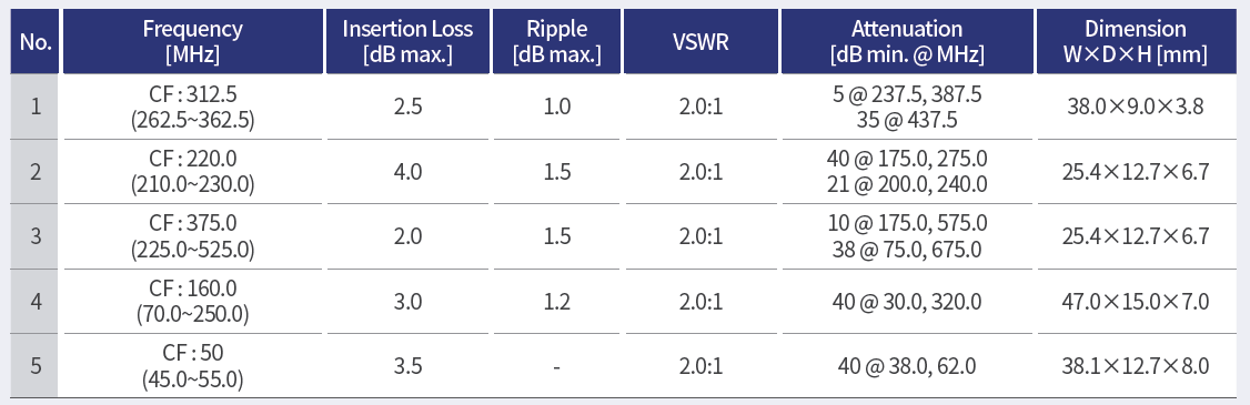
Demand reproducible RF evidence
A calibrated network-analyzer sweep establishes the filter’s small-signal transmission and reflection response under the stated conditions. Power, temperature, aging, and nonlinear behavior may require separate tests. Rohde & Schwarz’s passive-component guidance explains this distinction.
Ask for calibrated data with frequency span, resolution, source power, temperature, fixture, cables, adapters, reference planes, and de-embedding method. For a multiport device, state which unused ports are terminated and how isolation is calculated. Preserve Touchstone data when model correlation or system simulation is required.
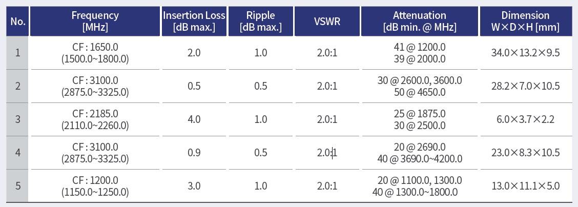
Tailor environmental and power testing
Do not copy a long list of military methods into a purchase specification. The official MIL-STD-810 record states that the document supports environmental tailoring based on system performance requirements rather than imposing universal tests. Build the profile from the real platform, storage, transport, and operating conditions.
Temperature can shift frequency response; vibration and shock can affect solder joints, resonators, connectors, and fasteners; humidity or salt can challenge finishes and seals. Define which RF checks are repeated before, during, and after exposure. Power testing should state waveform, duty cycle, duration, cooling, load mismatch, and allowable permanent or temporary change.
Evaluate evidence from a military RF filter manufacturer
Ask the military RF filter manufacturer for revision-controlled drawings, material and process controls, critical tolerances, inspection criteria, calibration records, sample traceability, nonconformance handling, and change notification. Clarify whether supplied plots represent a design sample, qualification lot, or production acceptance test. Define the sample plan and what raw data accompany each shipment.
Compare technical exceptions and evidence quality alongside price and lead time. Where qualification, production capacity, or delivery experience matters to the purchase, request records for the relevant product and scope.
Frequently asked questions
Is insertion loss the main filter metric? It is one important metric, but rejection, matching, isolation, power behavior, temperature shift, interfaces, and waveform effects may also control the design.
Does a scattering-parameter file prove high-power performance? No. Linear low-power measurements do not by themselves characterize heating, compression, arcing, or other power-dependent behavior.
What should a buyer approve with a military RF filter manufacturer before testing? Approve the test article configuration, reference planes, fixtures, conditions, sample count, data format, and pass/fail rules.
For broader context, review RF technology insights, RF antenna and component resources, and the applications hub.
Request an RF filter application evaluation.
References
Rohde & Schwarz — Passive Component Testing
MIL-STD-810 — Environmental Engineering Considerations and Laboratory Tests
https://quicksearch.dla.mil/qsdocdetails.aspx?ident_number=35978&lang=en
Related reading
Bandpass, Low-Pass, High-Pass and Notch RF Filters Explained
Understanding Key RF Filter Characteristics: Insertion Loss, Return Loss, Ripple, and Attenuation