
Read the measurement conditions first
RF filter characteristics are useful only when the measurement condition is visible. Insertion loss, return loss, ripple, and attenuation describe different parts of a response, but none is complete without frequency, impedance, reference plane, calibration, temperature, configuration, and acceptance context. Start by identifying the wanted band and the behavior the system must control.
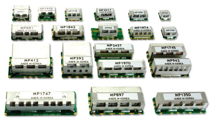
Use the same test article and interface when comparing suppliers. A change in connector, fixture, cable, termination, or temperature can move the apparent response even when the filter core is unchanged.
Separate transmission from reflection
Insertion loss describes the reduction in transmitted power under specified source and load conditions. Return loss describes the ratio of incident to reflected power at a port, expressed as a positive dB value. A higher return loss means less reflection; a lower insertion loss means less transmission loss.
For a two-port filter measured with matched reference impedances, a transmission trace of S21 = -2 dB corresponds to 2 dB insertion loss. A reflection trace of S11 = -20 dB corresponds to 20 dB return loss. These are illustrative values, not product measurements. State the port direction, reference impedance and sign convention beside the trace.
Use ripple to describe variation
Ripple is variation across a passband or other specified region. A filter can have acceptable average insertion loss but excessive variation at a sensitive channel edge. Define the interval, reference level, peak-to-peak or limit method, and whether the result is evaluated before or after fixture correction.
Do not call every slope a ripple value. The transition region and stopband attenuation are separate parts of the response. A buyer should know whether a reported number describes the passband, a corner, or a rejection point.
Interpret attenuation at a named frequency
Attenuation is meaningful when the frequency or region, source and load, and reference are named. For a notch or stopband, specify the blocker and the required reduction. For a low-pass or high-pass filter, state the first unwanted harmonic or low-frequency component that drives the decision. Avoid a single “attenuation” number that hides the sweep.
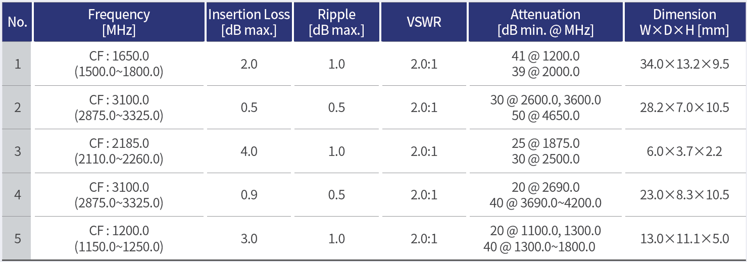
Keysight’s filter overview includes insertion loss, passband flatness, return loss, S-parameters, and dynamic-range considerations among common measurements for frequency-selective devices. Use those measures to build a response table that connects the wanted band, unwanted band, and acceptance limit.
Control reference plane and sweep
The reference plane tells the reader where the measurement begins. Record calibration method, connector, cable, fixture, de-embedding or adapter removal, sweep points, IF bandwidth, power, and averaging. If the filter is non-connectorized, explain how the fixture is represented and how its effect is treated.
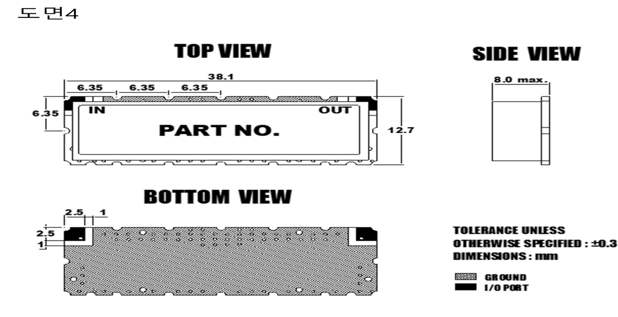
Temperature and configuration belong beside the trace. A filter with a tunable element, mounting bracket, cover, or external termination can have more than one valid response. Keep the article revision and assembly state in the data name.
Turn traces into acceptance decisions
Create a table with metric, frequency or band, reference condition, limit, observed result, uncertainty or repeatability note, and disposition. Separate a measured failure from an unresolved setup question. If the test boundary changes, repeat or qualify the comparison before editing the requirement.
For a filter review with MAC technologies Inc., provide the target response, impedance, interface, frequency sweep, temperature and configuration conditions, and the required data format.
RF technology insights offers broader context, while RF antenna and component resources and the applications hub organize the next measurement review.
Keep the buyer language precise
State which limits are contractual and which values are typical engineering information. Link the raw trace to each reported marker. A change in enclosure, connector or temperature requires a review of the affected measurements.
Keep a small glossary beside the acceptance table only when it clarifies the measurement. Define the reference direction, port, frequency interval, and sign convention used by the instrument. The glossary should support the data, not replace it. A buyer can then compare two reports without assuming that identical words were calculated from identical reference planes.
When limits are asymmetric, show the upper and lower bounds separately rather than collapsing them into one average. This is especially important for ripple and return loss near a passband edge.
References
10 Hints for Making Better Network Analyzer Measurements
Keysight — Scalar Network Analyzer: Migrating from Scalar to Vector Network Analyzer Systems, “Filters and Frequency Selective Devices,” pp. 13–15.
https://www.keysight.com/mx/en/assets/7018-09086/application-notes/5965-8166.pdf
https://www.keysight.com/ie/en/assets/7018-02338/technical-overviews/5990-4798.pdf