
Define the target response and tolerance
Custom RF filter frequency matching should begin with a response target that the communication system can verify. Define passband center and edges, stopband or blocker frequencies, transition regions, ripple, insertion loss, return loss, impedance, power, temperature, and allowable tolerance. Include the interface and reference plane so the target is not detached from the actual signal path.
On this page
Separate the requirement from the tuning method. The resonator, substrate, housing, coupling, and adjustment approach may change during development, but the acceptance boundary should remain visible.
Map the physical causes of drift
Material dielectric properties, conductor geometry, resonator dimensions, coupling gaps, covers, fasteners, and temperature can move a filter response. Record the material and stack-up assumptions, critical dimensions, surface finish, and assembly state. A frequency shift should be investigated against these variables before a tuner is adjusted by trial and error.
| Variable | What to control | Why it can move the match |
|---|---|---|
| Resonator geometry | length, gap, tolerance, finish | changes resonant frequency and coupling |
| Material | dielectric, conductor, adhesive, lot | changes electrical properties and loss |
| Coupling | spacing, alignment, adjustment range | changes bandwidth and ripple |
| Environment | temperature, enclosure, mounting | changes the installed response |
Keep the physical revision beside the RF trace. A result without the article state is not a reusable tuning record.
Tune with an explicit sequence
Start with a calibrated baseline and check fixture, connector, and cable before changing the filter. Adjust one controlled variable at a time, record the direction and amount of the change, and capture the response after each step. If a change improves the passband but harms rejection, retain both observations and decide against the full target rather than optimizing one marker.
Keysight documentation describes S-parameters and common network-analyzer measurements used for filter and passive-device evaluation. Use the relevant traces, markers, and sweep points to show what changed. Do not infer a production result from a single tuned sample.
Verify the test boundary
Reference plane, fixture, adapter, de-embedding, calibration, power, IF bandwidth, sweep density, and temperature belong in the data record. Rohde & Schwarz describes fixture characterization and de-embedding as a way to remove the effect of lead-ins and lead-outs from DUT measurements. Apply that principle only when the fixture model, calibration, and data support it.
If the filter is installed in a shield, module, or cable assembly, define whether the acceptance test covers the standalone filter or the production-intent path. Keep the two results separate when both are useful.
Confirm production-intent evidence
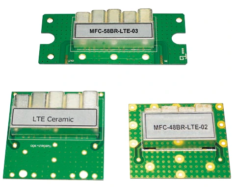
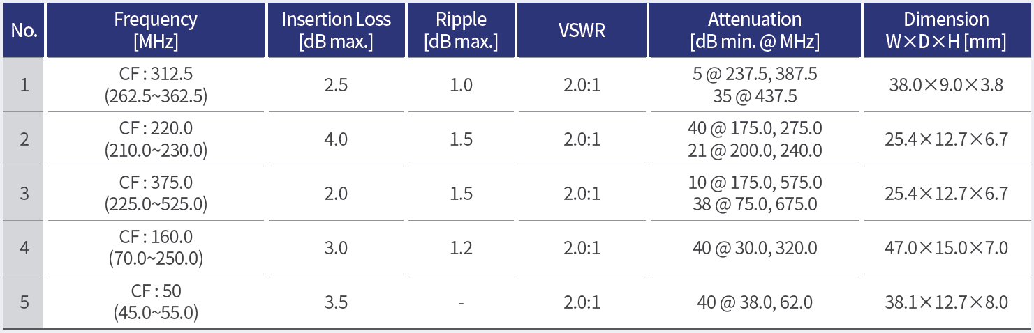
After tuning a prototype, verify the released drawing, materials, connector, cover, and adjustment state on a representative production-intent article. Repeat the agreed S-parameter sweep and compare passband, stopband, ripple, loss, and match with the target. Record sample identity, process or assembly notes, and any remaining tolerance.
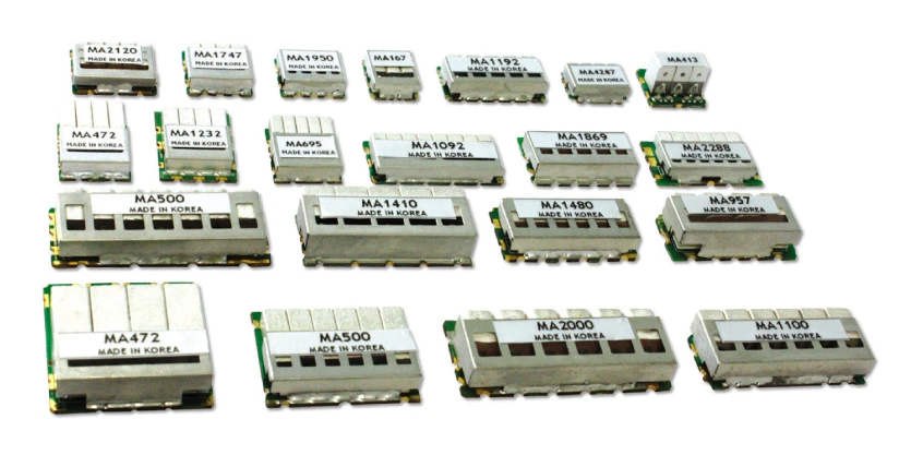
Production-intent verification should also define what happens when a material lot, drawing dimension, coupling feature, or process changes. A frequency-matching plan is incomplete without a change trigger.
For a custom filter review with MAC technologies Inc., provide the response target, tolerance, interface, material assumptions, tuning history, fixture definition, and production-intent acceptance plan.
RF technology insights provides related context, while RF antenna and component resources and the applications hub organize follow-up work.
Custom RF filter frequency matching is complete only when the production-intent article is checked against the released response target and tolerance record. Preserve that comparison when a material, drawing, or fixture changes.
Keep the tuning record reusable
Link the response target, sample revision, adjustment history, measured trace and release decision. If the operating band or enclosure changes, review the affected requirements before reusing the previous tuning result.
Before releasing the match, review the tolerance stack with mechanical and manufacturing owners. Identify which dimensions are tuned, which are fixed, and which can drift with material lot or assembly process. If a tuner remains in the released design, define its adjustment range, locking method, inspection point, and evidence needed after service. If the tuner is removed, preserve the final measured article and the process condition that produced it.
The frequency plan should also show how the filter interacts with the communication system. Mark the wanted channel, adjacent blocker, harmonic or spurious region, and the impedance seen at each port. A match that meets a narrow bench target but changes the system margin or isolation requirement is not a complete acceptance result. Keep the system response and component response distinguishable in the report.
If tuning requires a fixture or temporary cable, retain both the raw and corrected result when possible. Explain which one supports the requirement and which one is diagnostic. This preserves the reasoning behind the adjustment and gives the production team a way to investigate a later shift without repeating an undocumented trial-and-error sequence.
References
10 Hints for Making Better Network Analyzer Measurements
Accurate Test Fixture Characterization and De-embedding
https://www.keysight.com/mx/en/assets/7018-09086/application-notes/5965-8166.pdf