
RF filter performance testing is credible only when the device, fixture, calibration, sweep, power, temperature, and acceptance limits are identified. A clean plot without those conditions is difficult to reproduce and may hide a reference-plane or fixture difference. The practical goal is a measurement package that helps engineering, quality, and procurement reach the same decision.
On this page
Define the passband and stopband limits
Translate the system requirement into measurable passband and stopband limits. Define frequency ranges, insertion loss, return loss, rejection or attenuation, ripple, and any group-delay requirement that matters to the application. State which ports and signal directions apply. Separate a design target from a production acceptance limit so normal tolerance is not confused with a failure.
Power and temperature should be included only when relevant and supportable. If the filter will experience a specified continuous or peak power, duty cycle, or thermal range, record those conditions and the evidence expected. A small-signal room-temperature sweep should not be presented as proof of behavior outside the measured condition.
Establish calibration and the reference plane
The calibration method determines where systematic measurement errors are corrected. Record the vector network analyzer, calibration kit or electronic calibration unit, frequency span, ports, cables, adapters, and reference plane. Inspect connectors and stabilize cables before calibration and measurement. Recalibrate when the setup changes beyond the controlled state.
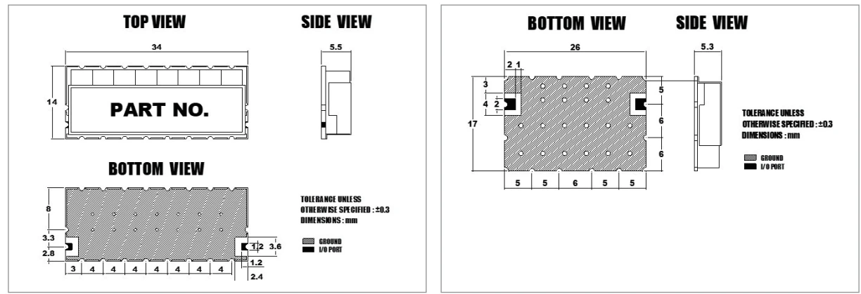
Fixtures need the same attention as the device. A fixture can add loss, mismatch, delay, and coupling. If de-embedding or port extension is used, retain the method and configuration. A golden or correlation unit can help reveal fixture drift, but it should not replace calibration or defined limits.
Choose sweep settings that can reveal the risk
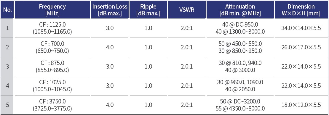
Frequency resolution must be fine enough to show narrow resonances, ripple, or transition behavior. Record the point count, intermediate-frequency bandwidth, averaging, source power, and smoothing state. Excessive smoothing can make a plot easier to read while obscuring real variation. Use consistent settings for comparisons.
The sweep should extend far enough beyond the passband to evaluate the specified rejection regions. If the instrument noise floor approaches the rejection target, record that limitation rather than treating the displayed trace as a precise device result.
| Measurement | Required context | Buyer decision supported |
|---|---|---|
| Insertion loss | path, passband, reference plane, temperature | wanted-signal budget |
| Return loss | port, band, fixture state | interface compatibility |
| Rejection | offset or stopband, noise floor, limit | blocker suppression |
| Ripple | window and resolution | amplitude consistency |
Review raw S-parameters, not screenshots alone
Retain the raw S-parameter file with sample identity, drawing and BOM revisions, fixture, calibration state and test date. Preserve the port numbering and reference impedance so the data can be interpreted correctly.
Limit lines should be linked to a controlled requirement. Review the full response as well as the pass/fail indicator, because an unexpected resonance outside the current limit may matter after integration. If a result is marginal, repeat the connection, verify the fixture, and compare another sample before assigning the cause.
Connect prototype testing to production acceptance
Engineering characterization can use detailed sweeps and multiple conditions. Production RF filter performance testing may need a shorter cycle, but it should retain correlation to the engineering method. Define which characteristics are measured on every unit, by lot, at first article, or after a change. Document fixture verification, sample handling, result storage, and disposition of failures.
Define the acceptance decision rule with measurement uncertainty and expected product variation in view. Keep the system requirement unchanged when choosing guard bands or internal process limits. Retain raw data and serial or lot identity, and use trends to investigate drift before it becomes a recurring failure.
Investigate deviations through a controlled loop
When a filter misses a limit, check the setup before changing the design. Confirm calibration, connector condition, cable stability, fixture seating, and sample identity. Then review material, geometry, tuning state, assembly, and enclosure contact. Record the root-cause hypothesis, corrective action, and retest condition.
Changes to resonators, coupling elements, substrate or ceramic material, connectors, housing, plating, soldering, or suppliers can require renewed correlation. The change-control plan should specify who approves the change and which RF evidence must be repeated.
For an RF filter performance testing discussion with MAC technologies Inc., provide the controlled requirement matrix, filter drawing, port definition, intended operating conditions, fixture information, raw traces, and acceptance logic. See RF antenna and component resources and RF technology insights for related engineering topics.
References
Keysight — Scalar Network Analyzer: Migrating from Scalar to Vector Network Analyzer Systems, “Filters and Frequency Selective Devices,” pp. 13–15.
https://www.keysight.com/ie/en/assets/7018-02338/technical-overviews/5990-4798.pdf