
MAC technologies Inc.’s equipment archive and January 2026 presentation document network analyzers, a planar near-field scanner and an absorber-lined antenna chamber. This article explains how those equipment types relate to RF development and what information a buyer should prepare for a measurement review. Confirm the current setup and applicable measurement method for the proposed work.
What the documented RF measurement facilities show
The documented equipment covers different measurement tasks: feed and component network analysis, spatial field sampling, and antenna characterization in a controlled space. The test plan should identify the relevant instrument, frequency range, fixture, software, calibration and sample configuration.
Network analysis: reflection and transmission
A vector network analyzer is generally used to measure complex S-parameters under defined frequency, source-power, calibration, cable, fixture, and port conditions. For an antenna, a conducted measurement can help review input match and complex impedance at the chosen reference plane. For a filter or diplexer, it can support transmission, reflection, rejection, and isolation analysis across relevant paths.
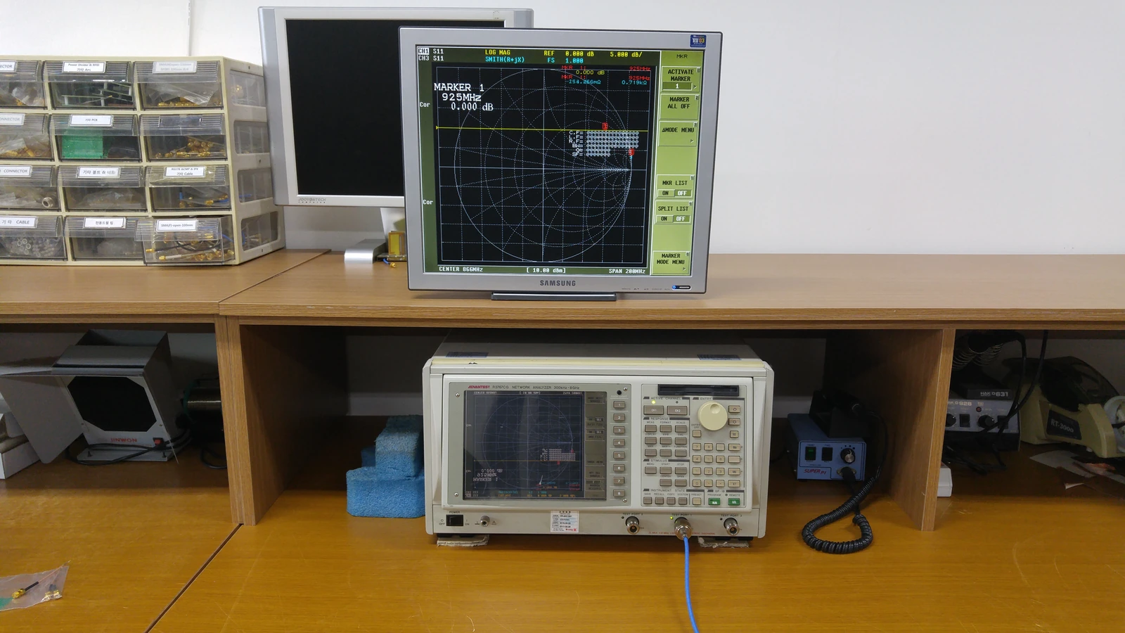
The useful record is not the instrument screenshot alone. It should include sample identity, drawing revision, calibration and reference plane, cable and fixture state, sweep settings, power, temperature when relevant, and the raw data file. The project must define which measured quantity supports which decision.
| Documented context | General engineering use | Project definition still required |
|---|---|---|
| Network analyzer | S-parameters, impedance, transmission and reflection | frequency range, calibration, fixture, limits |
| Near-field equipment | sampled electromagnetic field around an antenna | probe, scan geometry, processing, test volume |
| Antenna measurement-system context | controlled antenna characterization | method, configuration, uncertainty, acceptance |
Near-field scanning: spatial field data
Near-field systems sample the electromagnetic field over a defined geometry and may transform that data to derive other antenna characteristics. The result depends on the probe, scan surface, spacing, positioning, calibration, cables, processing assumptions, and environment. These parameters must be documented before results from different samples or revisions can be compared.
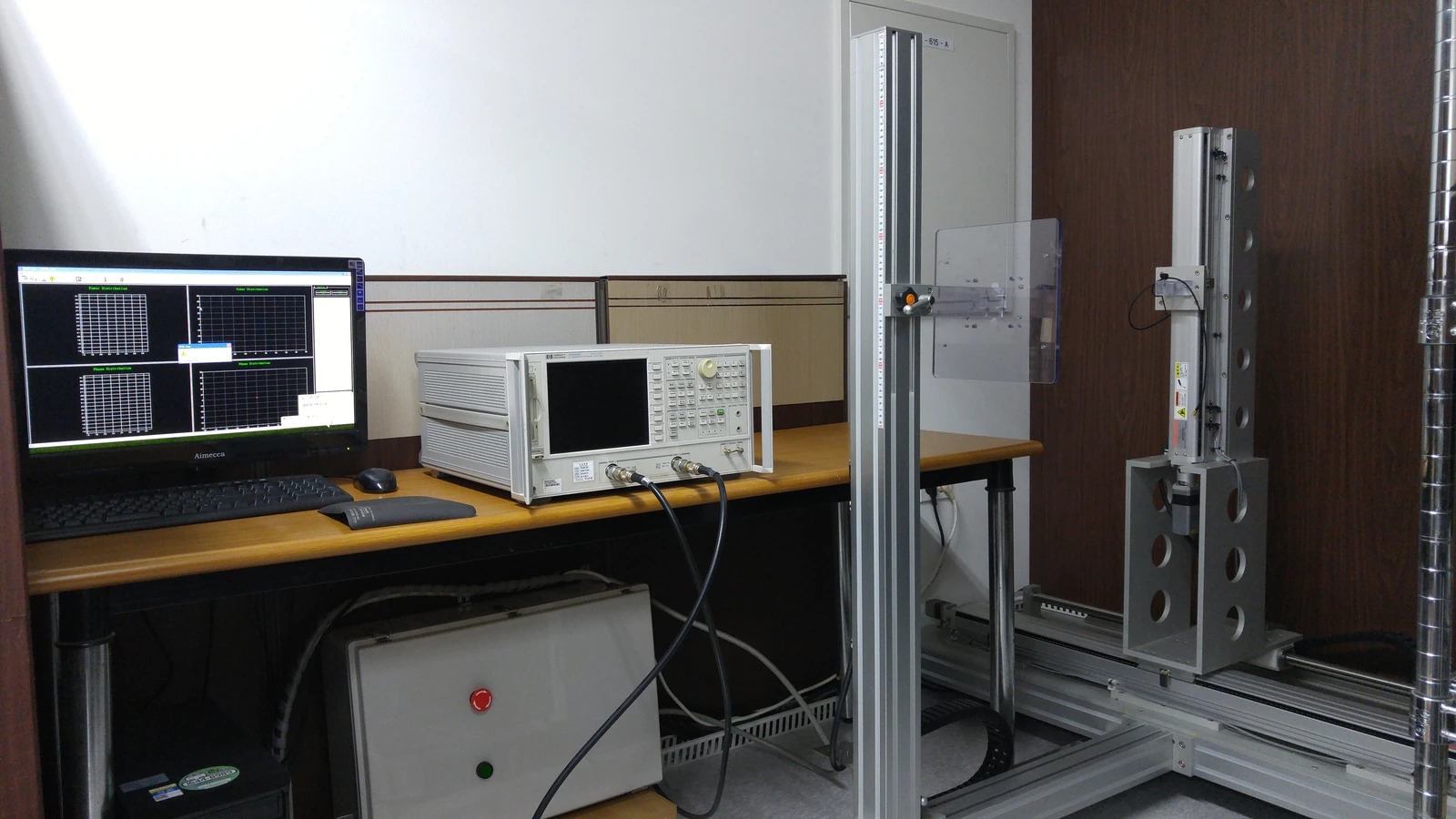
For a near-field test request, provide antenna size, operating band, connector and cable details, mounting condition, coordinate system and required output. Agree the scan area, probe, processing and uncertainty requirements before comparing results.
Antenna chamber measurements
A controlled antenna measurement environment can help reduce unwanted reflections and provide repeatable positioning, but the actual method depends on the facility and configuration. The equipment record should be paired with information about the test distance or scan geometry, absorber or surrounding environment, positioner, reference antenna, cables, polarization, alignment, and processing.
Design optimization using simulation tools is the first step in antenna development. After a prototype is manufactured, its actual performance must be verified using appropriate measurement systems. This process helps identify differences between simulation results and measured prototype performance, allowing the findings to be incorporated into further design improvements.
The combination of antenna design expertise and precise measurement systems improves both development accuracy and efficiency. Based on an integrated process of design, prototyping, measurement, and performance optimization, MAC technologies Inc. develops antenna solutions for a wide range of wireless communication environments.
IEEE Standard 149 provides guidance for antenna measurement practice. Use it to inform the method, then define the project configuration, uncertainty requirements and acceptance criteria.
Connect each measurement to a buyer decision
Measurement is most useful when it closes a named engineering question. A conducted feed check may help identify tuning or assembly drift. Pattern or field data may support comparison of orientation, housing, or bracket states. Installed validation may address a system-specific read zone or link condition. None of these should be substituted for another without explaining the limitation.
Define the baseline sample and the controlled variables before testing. If a housing, cable, connector, bracket, ground plane, or firmware-controlled radio state changes, identify whether the measurement must be repeated. Retain the conditions alongside the result so a later reviewer can understand the comparison.
Information to provide before requesting a measurement
Prepare the operating band, sample identifiers and quantity, electrical interface, mechanical drawing, cable, connector, installation state, orientation and environmental conditions. Specify the desired results, acceptance criteria, raw-data format and schedule. Resolve any unconfirmed test requirements before measurements begin.
Send this brief to MAC technologies Inc. for a review of the applicable equipment, measurement method, sample configuration and deliverables. Keep the agreed setup with the resulting data so later design changes can be compared on the same basis.
References
IEEE Standard 149
https://standards.ieee.org/ieee/149/6667/
Related reading
Military Antenna Environmental and RF Validation