
Define the test article and installation boundary
Military antenna environmental and RF validation is only interpretable when the article, fixture, exposure, and measurement boundary are controlled. Start by naming the antenna revision, materials, connector, cable, bracket, radome, mounting plane, and any platform representative structure. Record which items are production intent and which are laboratory substitutes.
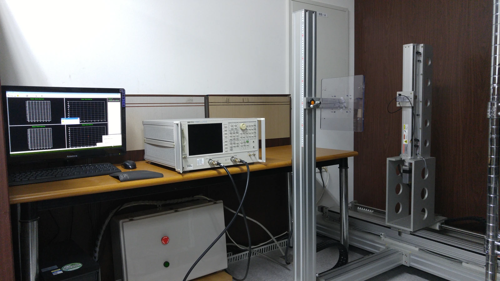
The validation plan should state the intended operating bands, polarization, impedance reference, power condition, RF metrics, environmental stresses, sequence, sample identity, and acceptance criteria. A standard can inform the method, but it does not supply a project-specific pass limit.
Tailor the environmental sequence
Define the mission and life-cycle conditions before selecting tests. Temperature, vibration, moisture, dust, shock, handling, or storage may matter differently depending on the platform and installation. The DLA ASSIST record for MIL-STD-810 describes an environmental tailoring process that results in realistic designs and test methods based on materiel performance requirements. Use that principle rather than copying every method into a generic checklist.
| Planning field | Question to answer | Evidence to retain |
|---|---|---|
| Exposure | Which life-cycle stress is credible? | tailoring rationale and sequence |
| Fixture | Does the fixture represent the boundary? | drawing, interface, and photos |
| Article | Which revision is tested? | serial or sample identifier |
| Acceptance | What changes are allowed? | pre-agreed RF and mechanical limits |
Do not describe an antenna as MIL-STD-810 certified solely because the standard appears in a plan. Certification and qualification require separate authoritative evidence.
Establish the pre-test RF baseline
Measure the agreed RF properties before exposure using a defined calibration, reference plane, fixture, cable, and environment. Depending on the antenna, record impedance or return loss, pattern or polarization, and any additional system metric required by the application. State the frequency points and instrument settings.
IEEE 149-2021 provides recommended practice for antenna transmitting and receiving-property measurements and discusses measurement facilities and instrumentation. Use it to make the baseline reproducible, then document project-specific limits and uncertainty.
Preserve sample and fixture traceability
Assign the sample, fixture, cable, fasteners, and enclosure a configuration identifier. Photograph or diagram the as-tested state, including orientation and service parts. If the exposure requires a chamber fixture or a modified connector, record the change and its relevance to the RF boundary.
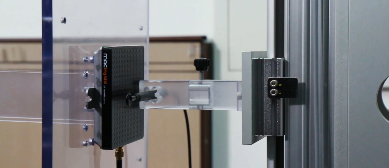
Keep the data file, setup sheet, calibration record, and observation log together. A later reviewer should be able to tell whether a change came from the antenna, the fixture, the cable, or the environmental exposure.
Compare after exposure without overinterpreting
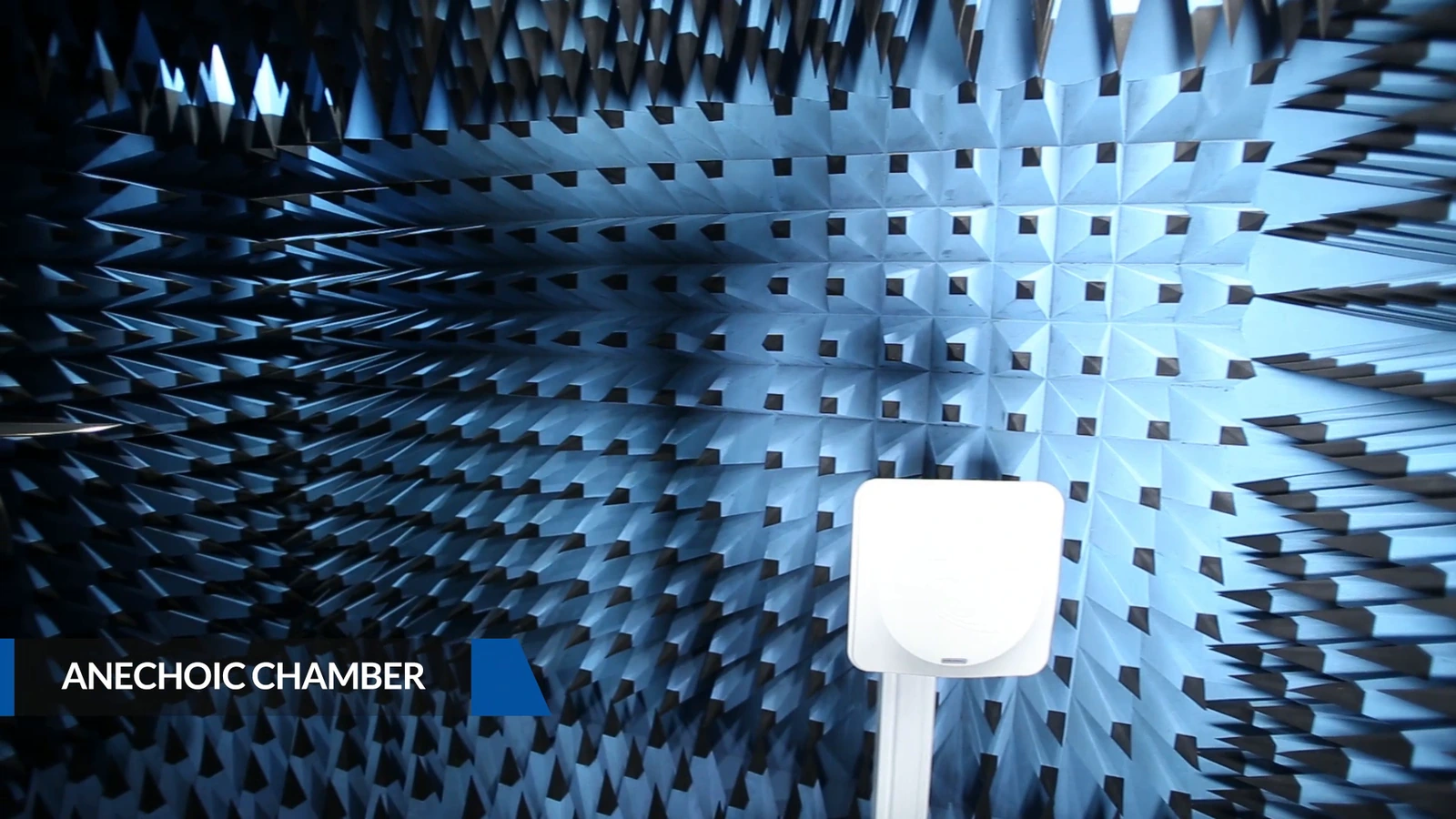
After the exposure, inspect the article and repeat the agreed RF measurements using the same reference condition. Compare the traces or measured values with the pre-test baseline and identify any change by frequency, polarization, orientation, or assembly state. If the fixture or cable changed, explain how that affects the comparison before assigning a disposition.
Report the result for the tested configuration and the acceptance limits used. Identify any additional platform or production verification needed before release.
Close with acceptance and disposition
The acceptance record should identify the article revision, environmental sequence, RF baseline, post-test comparison, deviations, photographs, instrument method, reviewer, and disposition owner. Define whether a deviation requires retest, drawing change, material review, or no action under the approved criterion.
For a validation review with MAC technologies Inc., provide the drawing, sample history, fixture definition, exposure rationale, RF baseline, and acceptance plan.
RF technology insights gives related context, while RF antenna and component resources and the applications hub organize the follow-up review.
Investigate changes before selecting a corrective action
If the result is outside the expected boundary, identify the changed variable before redesigning the antenna. Recheck the article identity, fixture, cable, calibration, exposure, and measurement condition. A controlled validation loop turns environmental and RF evidence into a defensible engineering decision without confusing a tailored test plan with a certification claim.
Before the chamber or field sequence begins, conduct a readiness review with the article owner, test engineer, and configuration owner. Confirm the sample label, drawing revision, fixture, cable, instrument calibration, data naming, exposure order, recovery time, and stop criteria. A short readiness record prevents a missing setup detail from becoming an unexplained post-test change.
When results are reviewed, separate observation from interpretation. “The trace shifted after exposure” is an observation; the cause may be a connector, material, fixture, moisture state, or antenna change. Record the investigation and disposition rather than rewriting the baseline. This discipline keeps a military antenna environmental and RF validation report useful to the next design revision.
Keep the report modular: one section for configuration and fixture, one for exposure, one for RF data, and one for disposition. A modular record makes it clear which observations are directly measured and which are engineering interpretation. It also lets a later reviewer compare only the changed exposure or article revision without losing the original baseline.
References
MIL-STD-810 — Environmental Engineering Considerations and Laboratory Tests
IEEE 149-2021 — IEEE Recommended Practice for Antenna Measurements
https://quicksearch.dla.mil/qsDocDetails.aspx?ident_number=35978
https://standards.ieee.org/ieee/149/6667/