
Impedance matching adjusts the impedance presented by an antenna and its feed network toward the system target over the required band. A low reflected-power reading at one frequency does not by itself establish bandwidth, radiation efficiency, gain or installed coverage. Evaluate both the feed match and the useful radiated performance in the final assembly.
On this page
Define the impedance-matching reference plane
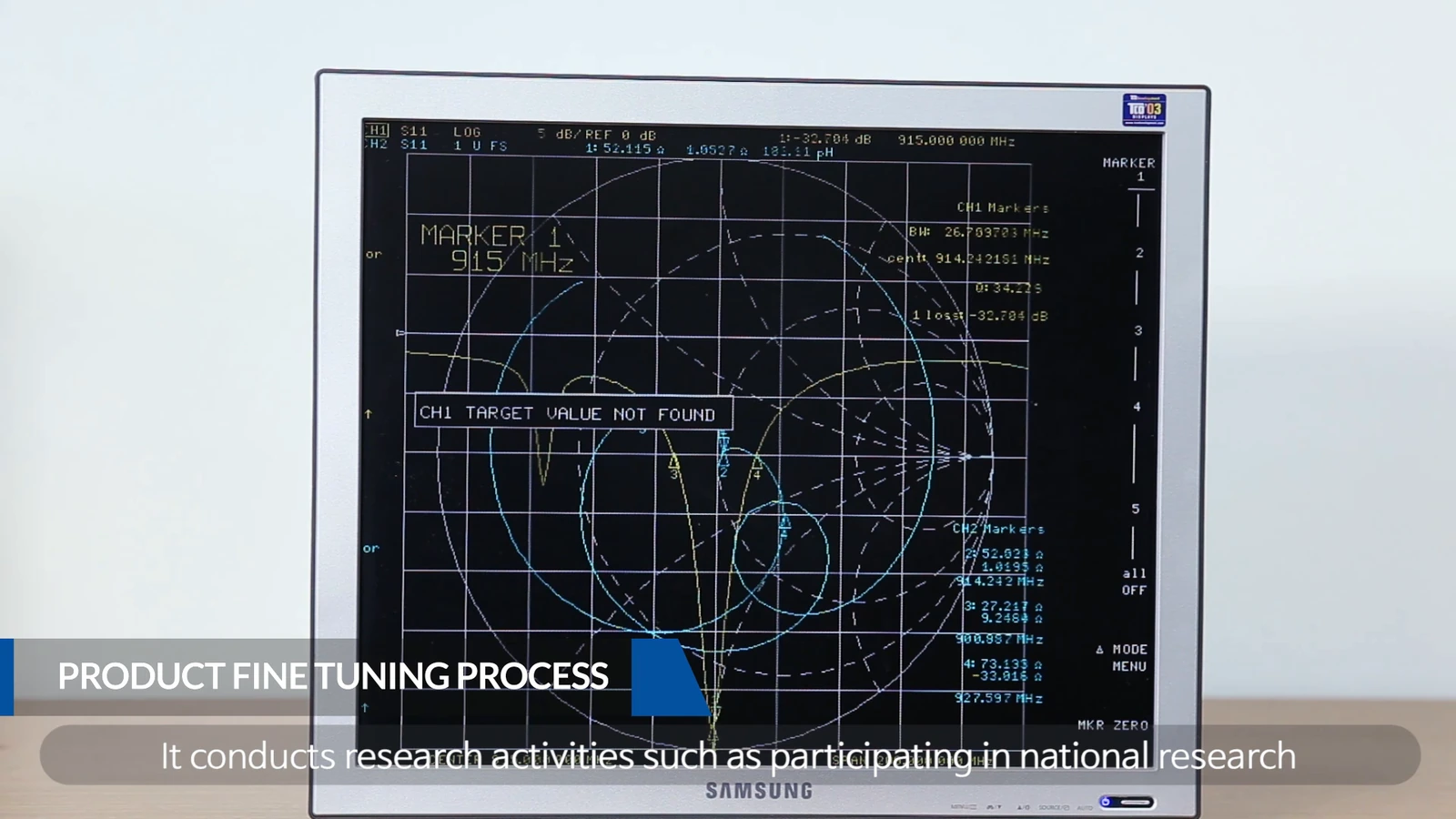
Every impedance result depends on where the measurement begins. State whether the reference plane is at the instrument, cable end, connector, matching network input, or antenna feed. Record calibration type, calibration date or state, fixture, cable, adapter, port extension, and any de-embedding method. Without this information, two Smith-chart traces may describe different parts of the system.
Complex impedance should be reviewed rather than reduced immediately to a single VSWR value. Resistance and reactance show how the antenna departs from the target and help determine whether geometry, feed position, or a matching network is the more appropriate variable. Return loss and VSWR are alternative views of reflection; neither measures the energy lost in a dissipative network.
Set a bandwidth objective before selecting a network
The target should cover the required band edges and operating conditions, not just a nominal center frequency. A narrow match can look excellent on one sample while becoming unreliable after normal material, assembly, or installation variation. Define the acceptance mask, relevant frequency resolution, and any regional-band requirements before optimization.
Matching-network choices introduce trade-offs. A simple L network may be compact, while additional sections can provide more degrees of freedom. Each component also brings tolerance, parasitic behavior, loss, power limits, and sourcing considerations. Distributed elements, geometry changes, or feed-location changes may be preferable when component loss or repeatability is a concern.
| Decision variable | What to document | Typical risk if omitted |
|---|---|---|
| Reference plane | calibration, fixture, cable, connector | misleading comparison |
| Matching topology | component values, package, tolerance, layout | loss or sample variation |
| Bandwidth | center, edges, acceptance mask | over-optimized single point |
| Installed state | enclosure, bracket, battery, cable, nearby metal | field detuning |
Expect the enclosure and cable to participate
The antenna rarely operates as an isolated component. A bracket, battery, display, PCB ground, adhesive, radome, cable route, or nearby conductive surface can change effective electrical length and current distribution. The same applies to a person, vehicle structure, cabinet, or product housing near the radiator.
For that reason, initial tuning can begin on a controlled bench fixture, but final impedance matching should be verified in the intended assembly. Keep cable type, length, routing, connector torque, enclosure state, and mounting orientation consistent. If the product has multiple approved installation states, evaluate each state or define a bounded installation rule.
Use a disciplined VNA workflow
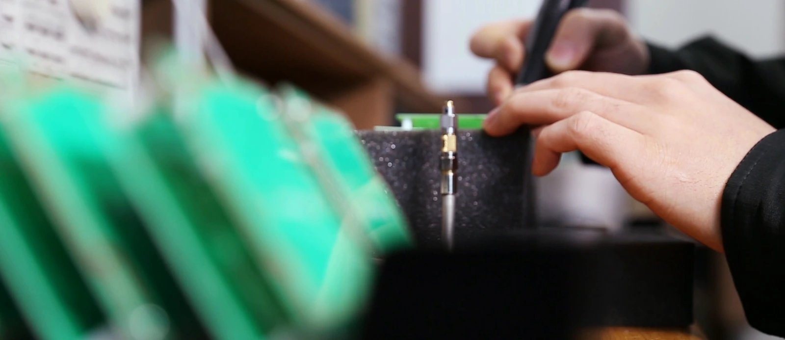
A vector network analyzer measures magnitude and phase, allowing the engineer to review S-parameters and complex impedance. Start with an appropriate calibration for the frequency range and connection method. Minimize unnecessary adapters, stabilize cables, and avoid moving them between comparative measurements. Use instrument power and averaging settings that suit the passive device and the required noise floor.
Save raw traces with the sample identifier, drawing revision, matching-network revision, fixture, and environmental condition. ETSI TR 102 273-2 provides practical antenna-measurement context, including why test configuration and positioning belong in the record.
Correlate matching with radiation performance
A better return-loss trace does not always produce a better system. A lossy network can reduce reflection while converting energy to heat, and an installed antenna can show an acceptable feed match with an unsuitable radiation pattern. Correlate impedance data with the radiation or application metric that matters: efficiency, gain, pattern, polarization, read zone, or link margin.
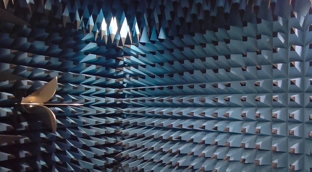
When the design changes, compare both the feed behavior and the system-level result. This is especially important when tuning is performed near the edge of the available enclosure volume or when the product depends on a ground plane that varies between installations.
Plan tolerance and repeatability
Review component tolerances, substrate properties, adhesive thickness, connector position, feed geometry, enclosure dimensions and assembly variation. Check representative builds and approved installation states before setting production limits. Define the verification needed for substitute parts; equal nominal values do not guarantee equal RF behaviour.
For an impedance matching review with MAC technologies Inc., provide the target band, source impedance, mechanical envelope, ground arrangement, cable and bracket state, existing VNA files, and the decision criteria that will be used after installation. See the RF technology insights and applications hub for related integration topics.
References
ETSI TR 102 273-2
https://www.etsi.org/deliver/etsi_tr/102200_102299/10227302/01.02.01_60/tr_10227302v010201p.pdf