
Moving from RF simulation to mass production requires the model assumptions to be translated into drawings, materials, prototypes, measurements and production controls. Simulation helps explore design sensitivity. Representative hardware builds then test whether the response can be reproduced with the intended materials and assembly process.
Agree the requirements and acceptance method
The first gate is a requirement baseline that engineering, procurement, and manufacturing can all interpret in the same way. Record the operating band, usable bandwidth, impedance, polarization, power, mechanical envelope, connector, cable, mounting surface, nearby materials, and environmental conditions. Separate mandatory acceptance limits from design preferences and open questions.
This baseline should also define how success will be measured. A statement such as “good antenna performance” is not testable. A useful brief identifies the installed configuration, measurement reference plane, sample condition, test environment, and evidence expected at each review. If a requirement remains uncertain, keep it visible instead of hiding it in a model assumption.
Make simulation assumptions reviewable
A reproducible RF model needs more than geometry. Document material properties and tolerances, conductor treatment, ports, boundaries, mesh settings, excitation, cable or feed representation, and the revision of every imported drawing. Record whether dielectric values are nominal, supplier-controlled, or measured. The model should make clear which parts of the final assembly are represented and which are simplified.
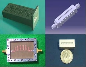
Sensitivity work is often more useful than a single optimized result. Vary the dimensions, material properties, gap, feed position, connector model, and nearby metal that are realistically expected to move in production. This identifies parameters that need tighter control and parameters that can tolerate normal variation. It also prevents a nominal simulation plot from being mistaken for a production guarantee.
Freeze production-intent interfaces before prototyping
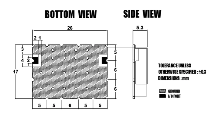
An early proof-of-concept may use convenient connectors, cables, substrates, or fixtures. Before correlation, the prototype should move toward the intended material stack, connector, bracket, cable exit, enclosure, fasteners, adhesive, and ground interface. These elements can change current distribution, impedance, resonance, and radiation behavior.
Each prototype should be tied to a drawing revision, bill of materials, assembly record, and configuration photograph. If a tuning component or geometry is adjusted, record the previous state, the change, and the resulting measurement. Without this chain, a successful prototype cannot be reproduced or explained.
| Engineering gate | Required evidence | Decision supported |
|---|---|---|
| Requirement review | operating conditions, interfaces, limits, open items | whether the design problem is defined |
| Model review | assumptions, boundary conditions, sensitivity results | whether the model is suitable for decisions |
| Prototype review | drawing, BOM, assembly state, measured traces | whether simulation and hardware correlate |
| Production release | controlled files, tolerances, inspection points, test method | whether the design can be repeated |
Correlate the prototype rather than forcing agreement
Compare simulation and measurement under equivalent conditions. Confirm the reference plane, cable, fixture, enclosure, bracket and sample orientation. Investigate frequency shifts against material tolerance, connector modelling, adhesive, cable routing and assembly differences. Use representative builds to test whether the explanation holds beyond one prototype.
Use measured results to improve the model and the release controls. Do not tune the model only until it resembles one sample. The useful outcome is an explanation that remains credible across additional builds and expected variation. For antenna measurements, IEEE Standard 149 provides recognized measurement-practice context; the project still needs its own configuration and acceptance definitions.
Convert tolerance learning into production controls
Put variables that materially affect RF response into drawings, material specifications, work instructions or inspection plans. Examples include substrate thickness, dielectric tolerance, critical gaps, feed location, connector seating, solder volume and cable route. Choose each tolerance to control a defined risk and specify how it will be inspected.
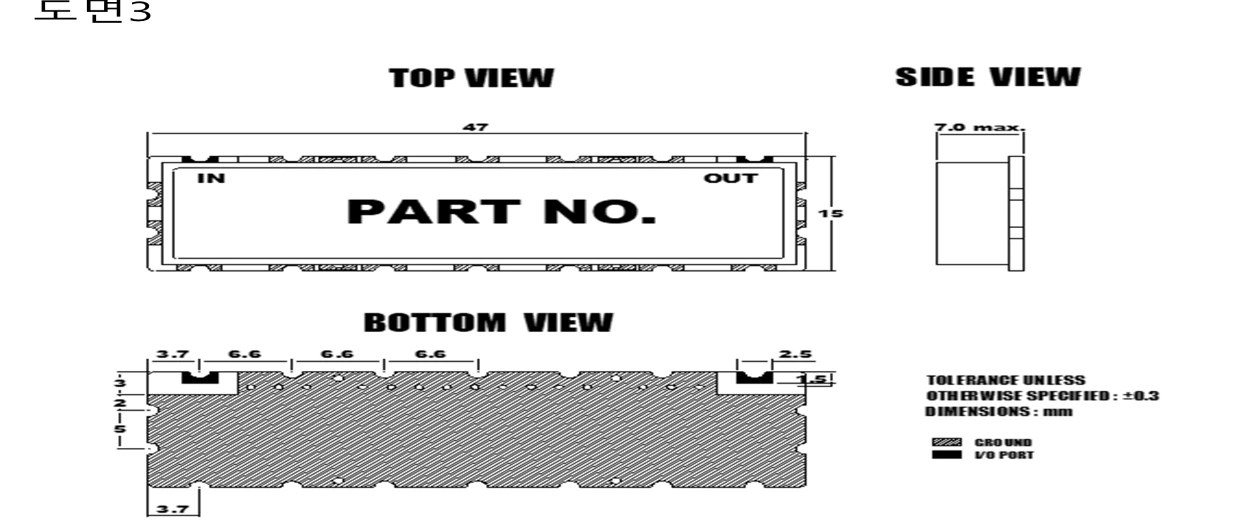
Production test also needs a defined role. A rapid conducted check may detect assembly drift, but it does not automatically replace radiation or installed-system validation. Decide which characteristics are verified on every unit, by sampling, at first article, or after a controlled change. Retain raw data and sample identity when the evidence will support later comparison.
Release the complete technical package
The release package should connect the approved drawing and BOM to the test method, limits, fixtures, software or instrument settings, inspection points, and deviation process. Change control should identify which RF checks must be reopened when a material, geometry, connector, cable, enclosure, or process changes.
For a development review with MAC technologies Inc., provide the operating requirements, mechanical files, intended materials, prototype revision, measurement data, expected quantities and decision dates. Identify which inputs are confirmed and which remain provisional.
References
IEEE Standard 149
https://standards.ieee.org/ieee/149/6667/