
Start with the ports and frequency bands
A typical two-port RF filter controls one transmission path. A diplexer has a common port and two frequency-selective branches, allowing different bands to share an antenna or cable. It can separate the bands or combine them through the same passive network.
Draw the source, load, wanted bands, blockers, and power conditions. A single path may need a two-port filter. Two non-overlapping frequency paths sharing a port may call for a diplexer; compare the required branch responses and isolation.
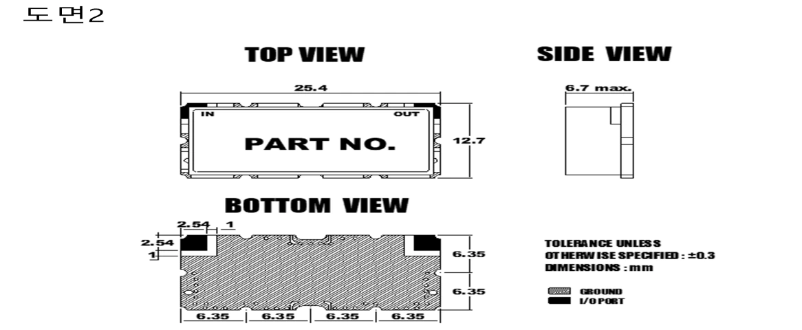
Compare topology, not labels
| Question | RF filter | Diplexer |
|---|---|---|
| Port view | defined input and output path | common port plus separated branches |
| Main decision | shape one response | combine or separate two paths |
| Interaction | surrounding source and load | branch interaction and common-port behavior |
| Evidence | passband, stopband, loss, match | branch responses, isolation, common-port behavior |
The terms are not a claim about construction technology. A diplexer contains frequency-selective networks, but its system risk includes how those networks interact through the common port.
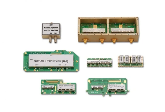
Define passband relationships and isolation
Record each branch passband, transition region, stopband, and the separation between them. Ask what happens at the edge of one branch while the other branch is active. Isolation is a system requirement, not merely a label on a diagram. It can be affected by termination, mismatch, fixture, cable, and the common-port environment.
For a simple filter, the key question may be attenuation at a blocker. For a diplexer, also ask how energy from one branch appears at the other branch and what the common port sees across both bands. Keep the rejection and isolation limits separate so a strong single-branch response does not hide a weak inter-path boundary.
Include terminations and power conditions
Specify source and load impedance at every port, the expected termination when a branch is inactive, and the power or duty condition. A branch that is open, mismatched, or connected to an active transmitter can produce a different response from the same branch measured with a laboratory termination.
If the diplexer is used with a shared antenna or duplexed radio, include the antenna, switch, cable, and connector transitions in the integration view. For a standalone filter, include the upstream and downstream network that defines the real reference condition.
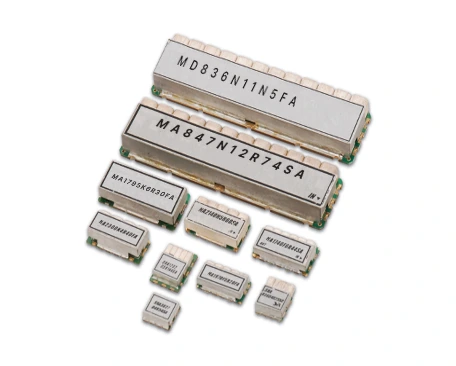
Build a measurement plan that matches the network
For a two-port filter, S11 and S22 describe port reflections, while S21 and S12 describe transmission. Characterize a diplexer with a three-port measurement or a controlled sequence of two-port measurements, using the specified reference impedances and matched terminations at unused ports. Evaluate expected installed mismatches separately. Record calibration, reference planes, frequency sweep, power, and temperature.
Rohde & Schwarz describes fixture characterization and de-embedding as a way to remove lead-in and lead-out effects from DUT measurements. Use that concept when connectors, launches, or test fixtures would otherwise obscure the common-port or branch result. Do not claim a measurement is de-embedded unless the setup and data support it.
Support a buyer decision
For a review with MAC technologies Inc., provide the port diagram, band plan, terminations, loss and isolation limits, power conditions, and mechanical interfaces. Specify whether acceptance covers the component, a module, or the complete installed path.
RF technology insights gives supporting context, while RF antenna and component resources and the applications hub organize the next system review.
Keep branch evidence separate
The final record should show the common-port response, each branch response, isolation, terminations, fixture, and disposition of deviations. If the system topology changes, revisit the filter-versus-diplexer decision rather than keeping the original component label. The correct comparison is the one that follows the signal flow through the complete network.
For a buyer review, add a port map and a test-state table. Show which branch is driven, which branch is terminated, what the common port connects to, and which S-parameter or isolation result closes that state. This prevents a two-port branch measurement from being presented as proof of the complete diplexer behavior and makes a later integration change easier to scope.
The review should also distinguish a diplexer from a filter followed by an external splitter or combiner. Draw the signal flow, specify where matching and isolation are evaluated, and state which losses belong to the filter assembly versus the surrounding network. That prevents a topology decision from being made only from similar-looking frequency plots.
For a shared antenna, add the antenna match and cable path to the integration boundary. A diplexer can look balanced in a fixture while the installed common port sees a different termination. Record that condition before accepting branch data, and state whether the acceptance test is component-level, module-level, or full-path.
Use the same port names on the drawing, setup sheet, and measurement files.
References
Measurement Parameters — Keysight Network Analyzer Help
Accurate Test Fixture Characterization and De-embedding
https://helpfiles.keysight.com/csg/NA520xA/S1_Settings/Measurement_Parameters.htm
Three-port measurement context: Rohde & Schwarz, 3-Port Measurements, https://cdn.rohde-schwarz.com/pws/dl_downloads/dl_application/application_notes/1ez26/1ez26_1e.pdf