
An RFID antenna specification is useful only when every value has a defined condition and acceptance method. Engineering teams should state the regional band, impedance reference plane, polarization, pattern requirement, cable and connector, physical envelope, environment, and installed test before comparing antennas. This turns a list of catalog numbers into a controlled system requirement.
The specification should not promise a read distance in isolation. Reader settings, cable loss, antenna placement, tag sensitivity, tag orientation, tagged material, reflections, and interference all influence the result. Final antenna selection should be based on the defined application, installation conditions, and evidence measured against the agreed specification.
What radio and protocol context comes first?
Identify whether the project uses UHF, HF, or another RFID implementation, then cite the applicable air interface and regional rules. For passive UHF systems, the GS1 EPC UHF Gen2 protocol defines physical and logical communication requirements for interrogators and tags across 860 MHz to 930 MHz. A product specification must narrow that broad range to the market and equipment configuration being designed.
For European UHF RFID equipment, ETSI EN 302 208 V3.4.1 addresses equipment operating in the 865 MHz to 868 MHz and 915 MHz to 921 MHz bands under defined power conditions. The standard is an input to compliance planning, not a substitute for identifying the finished product, country, antenna configuration, and applicable assessment.
Specify electrical values as a connected set
A practical comparison table should include:
frequency range and allowed variation across temperature and production
nominal port impedance and the measurement reference plane
return loss or VSWR limit, bandwidth definition, and test fixture
linear or circular polarization, axial ratio where relevant, and orientation
realized gain or gain pattern with coordinate system and cable treatment
maximum input power and duty assumptions
Use the following matrix to record the values, conditions, and acceptance methods for the intended application.
| Specification Item | Requirement to Record | Condition or Reference | Application Acceptance Evidence |
|---|---|---|---|
| Frequency and regional band | Intended market, operating range, and allowed variation | Reader regional configuration and applicable equipment conditions | Confirm the complete reader, cable, and antenna configuration over the required band |
| Impedance | Nominal or complex target, as applicable | Connector, feed, probe, or other agreed reference plane | Calibrated complex measurement from the stated plane |
| Return loss or VSWR | Limit and bandwidth over which it applies | Fixture, cable treatment, installation state, and temperature where required | Traceable sweep data for representative production-intent samples |
| Polarization | Linear or circular state, orientation, handedness, and axial-ratio requirement where relevant | Frequency and angular region used by the read zone | Polarization evidence plus tagged-item tests over expected orientations |
| Pattern and gain | Coverage angles, exclusion zones, and gain context | Coordinate system, frequency, mounting, cable loss, and whether values are realized | Pattern data and installed read-zone verification |
| Cable and connector | Type, length, loss allowance, routing, and mating interface | Minimum bend radius, strain relief, and production assembly | Inspection and loss or continuity checks on the intended assembly |
| Mounting and environment | Envelope, fasteners, ground, nearby materials, ingress, and justified environmental limits | Production-intent enclosure and installation drawing | RF and mechanical recheck after installation and applicable conditioning |
| Application acceptance test | Tags, materials, orientations, speed, desired reads, and unwanted-read zones | Reader model, firmware, port power, cable, site geometry, and sample count | Recorded pass/fail results with raw data and configuration revisions |
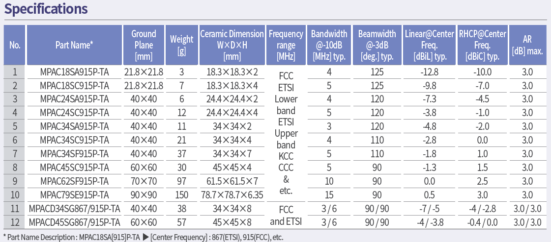
Peak gain alone does not define coverage. Ask for pattern cuts or three-dimensional data appropriate to the read zone, and state whether cable loss is included. The IEEE 149-2021 antenna measurement practice provides a recognized framework for radiation-pattern measurements and test-facility considerations.
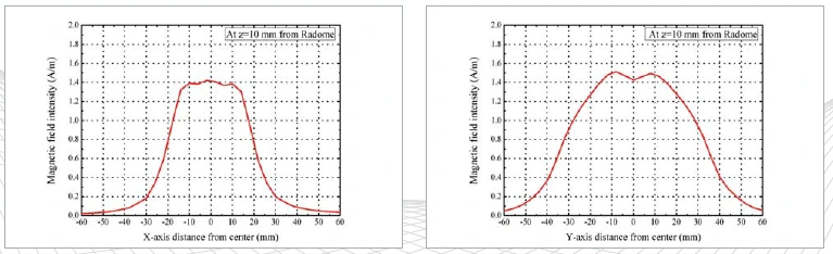
Connect mechanical details to RF behavior
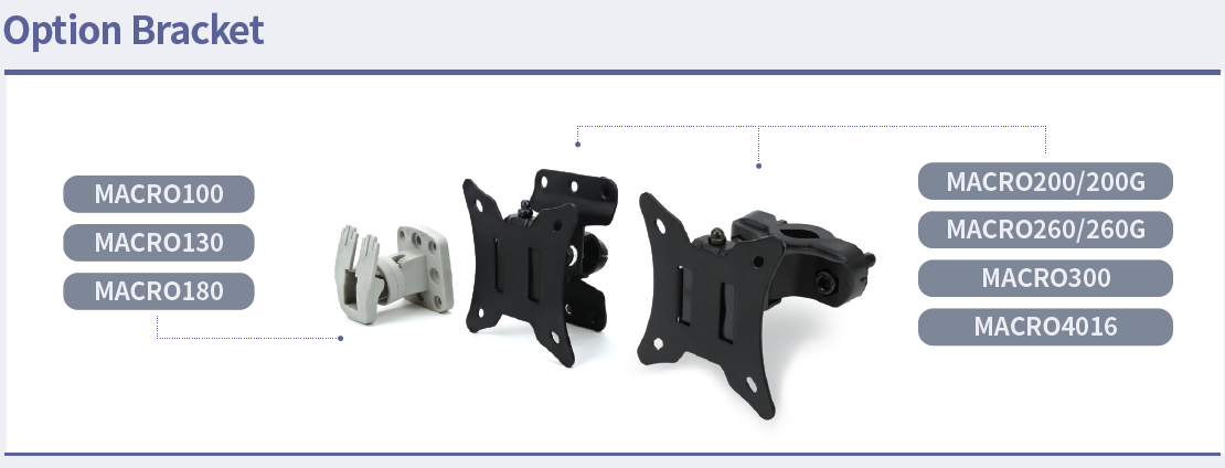
An RFID antenna specification should also record antenna dimensions, connector position, cable bend limits, mounting holes, grounding method, radome material, ingress protection target, and nearby keep-out zones. The installation drawing should show distance from metal, walls, conveyors, batteries, or other antennas. These are not secondary details: changing them can detune the port or reshape coverage.
Define drawing revision and change-control rules. If a supplier changes a substrate, adhesive, cable, connector, housing resin, or mounting bracket, the team should know which measurements must be repeated.
Turn the document into an acceptance plan
Verify the specification at both component and application levels. Component checks cover dimensions, connector quality, return loss or VSWR, and relevant radiation data. Application checks use the intended reader, software settings, tagged items, orientations, speeds, and surrounding materials. Record successful reads and unwanted reads outside the target zone.
Use production-intent samples and preserve raw data, calibration information, fixture details, firmware settings, and test dates. A numeric requirement without this context is difficult to reproduce or audit.
Frequently asked questions
Which specification should be written first? Start with band, installation geometry, read zone, tagged items, and acceptance criteria; those choices determine which antenna values matter.
Is a low VSWR enough? No. Feed match is important, but it does not by itself establish radiation efficiency, pattern, polarization, or read-zone performance.
Can one specification cover every country? Not safely by assumption. Confirm the applicable regional spectrum and finished-equipment requirements for each target market.
For related engineering context, use RF technology insights, the RF antenna and component resources, and the applications hub.
Request a review of an RFID antenna specification.
References
GS1 EPC UHF Gen2 Air Interface Protocol
ETSI EN 302 208 V3.4.1
IEEE 149-2021 — IEEE Recommended Practice for Antenna Measurements
https://www.gs1.org/standards/rfid/uhf-air-interface-protocol
https://www.etsi.org/deliver/etsi_EN/302200_302299/302208/03.04.01_60/en_302208v030401p.pdf
https://standards.ieee.org/ieee/149/6667/
Related reading
Understanding RFID Antenna Characteristics: How to Read a Datasheet