
Choose linear polarization when tag orientation is controlled and matched coupling is the priority. Circular polarization can help when a linear tag rotates within the plane transverse to propagation, provided the link has enough margin. Confirm the choice with representative tagged items and the intended read zone.
Polarization describes the orientation and time behavior of an electromagnetic field. Maximum transfer occurs when transmitting and receiving polarization states are matched; mismatch reduces the received power available to the passive tag and the backscattered signal available to the reader. Reflections and nearby materials can further change the installed field. Read-zone performance should therefore be validated with the actual antenna, tags, materials, reader configuration, orientation range, and installation geometry.
When linear polarization fits
In a linearly polarized wave, the electric-field vector at a fixed point oscillates along one fixed axis. A reader antenna with this polarization suits applications with controlled tag alignment, such as a conveyor, fixture, or document path.
The risk is orientation sensitivity. Rotate a linearly polarized tag relative to the reader field and the polarization match changes. Mechanical tolerances, package rotation, item presentation, and operator behavior therefore belong in the requirement.
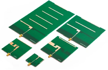
Linear and circular polarization compared
| Property | Ideal linear polarization | Ideal circular polarization |
|---|---|---|
| Electric field at a fixed point | Oscillates along one fixed axis | Vector rotates in the plane normal to propagation |
| Orthogonal components | Components combine along a fixed line | Equal amplitudes with a 90 degree phase difference |
| Linear tag antenna | Best polarization alignment when axes align | Ideal polarization coupling is one-half in power regardless of in-plane rotation |
| What still matters | Misalignment, tilt, pattern and installation | Handedness, axial ratio, tilt, pattern and installation |
This comparison describes polarization, not the physical outline of an antenna. The circular-to-linear statement assumes an ideal wave and a linear tag rotated in the transverse plane; it does not remove all tag-orientation or read-range effects.
When circular polarization fits
Circular polarization can reduce sensitivity to in-plane rotation of a linear tag. For an ideal circular wave and an ideal linear receiving antenna, polarization coupling is one-half of the aligned linear-to-linear power, a 3 dB loss on that link. Include this in the link budget; it is not a fixed prediction of RFID read range.
Circular polarization also needs a defined handedness and axial-ratio performance over the required beam and band. A catalog label alone does not show how the polarization behaves at every angle in the installed read zone.
| Factor | Linear Polarization | Circular Polarization |
|---|---|---|
| Field behavior | At a fixed point, the electric-field vector oscillates along one fixed axis | Field orientation rotates with a defined handedness; practical antennas require axial-ratio context |
| Tag orientation condition | Best coupling requires the tag polarization to remain suitably aligned with the reader field | Can reduce sensitivity to tag rotation when the antenna, tag, pattern, and link otherwise support the read |
| Main advantage | Efficient matched coupling in controlled-orientation applications | Greater tolerance when tag orientation varies within the intended read zone |
| Main risk | Rotation, presentation tolerance, or installation error can create severe polarization mismatch | Handedness, axial ratio, pattern variation, zone overlap, and link-budget trade-offs can be overlooked |
| Validation variable | Tag angle, antenna mounting axis, path, material, and off-axis position | Tag angle, handedness, axial ratio over frequency and angle, pattern, and reflections |
| Typical application context | Fixtures, conveyors, or document paths with repeatable orientation | Portals, shelves, bins, or manual presentation where orientation is less controlled |
These are application contexts rather than universal performance rankings. A linearly polarized antenna is not automatically the higher-performing product, and a circularly polarized antenna is not automatically the longer-range product. Installed pattern, polarization match, materials, reader configuration, cable loss, and acceptance geometry determine the result.
Compare polarization across the usable beam
Request co-polar and cross-polar measurements, or equivalent polarization data, over the frequencies and angles used by the application. Record the coordinates, mounting, cable treatment, and uncertainty. IEEE 149-2021 provides antenna-measurement context.
Record at least:
tag polarization and expected orientation distribution
reader-antenna polarization, handedness, and axial-ratio requirement
gain or realized-gain pattern over the usable read zone
mounting angle, nearby metal, walls, floor, and other antennas
cable loss, reader configuration, and acceptance thresholds
Do not compare only boresight gain. Tags may pass through off-axis regions where pattern shape, polarization purity, and reflections differ from the nominal centerline.
Validate orientation as a controlled variable
The GS1 TIPP test-configuration guideline provides repeatable orientation and placement conventions for tagged-item grading. Use clearly recorded tag location, item orientation, support position, and measurement geometry so the application trial can be repeated.
Build a matrix of representative tag types, materials, orientations, heights, and travel paths. Measure desired reads, missed reads, and unintended reads. Repeat the matrix after enclosure, mounting, and site conditions are final.
Include boundary orientations and off-axis positions because a configuration that passes at boresight may fail at the edge of the intended zone at representative operating speeds.
Frequently asked questions
Is circular polarization always safer? No. It can improve orientation tolerance, but pattern, axial ratio, link budget, reflections, and zone overlap still matter.
Can antenna polarization fix an unsuitable tag location? Not necessarily. Metal, liquid, shielding, or poor tag placement may dominate the result.
Should polarization be specified without a pattern? No. The requirement should cover polarization behavior over the angles and frequencies that the application uses.
For more context, see RF technology insights, RF antenna and component resources, and the applications hub.
Compare polarization options for an RFID read zone.
References
IEEE 149-2021 — IEEE Recommended Practice for Antenna Measurements
GS1 TIPP Tagged-Item Grading: Test Configuration Guideline
https://standards.ieee.org/ieee/149/6667/
https://ref.gs1.org/guidelines/tipp/test-configuration/
Polarization definitions and ideal coupling: https://www.antenna-theory.com/basics/polarization.php
Related reading
Custom RFID Antenna Frequency and Impedance Matching