
UHF RFID antenna selection for a European project begins with the applicable band, permitted equipment conditions, deployment country, and finished-product compliance route. After that, match polarization, beamwidth, gain pattern, enclosure, cable loss, connector, and mounting to the read zone. Validate representative tagged items before fixing antenna count, placement, or reader settings.
Record the deployment countries and the reader configuration early. Fixed readers, handheld devices, portals, and embedded systems need different coverage and installation plans, even within the same regional band.
Which air interface and regional band apply?
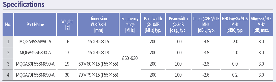
The GS1 EPC UHF Gen2 air-interface protocol defines communication between interrogators and passive tags across 860 MHz to 930 MHz. A European design must narrow that range to the applicable equipment and deployment conditions rather than assuming that an antenna or reader configuration is globally interchangeable.
ETSI EN 302 208 V3.4.1 covers RFID equipment operating in the 865 MHz to 868 MHz and 915 MHz to 921 MHz bands under specified power levels. Engineering and compliance teams should check the current harmonised-standard status and applicable national conditions for the finished equipment.
Design the read zone before choosing gain
For UHF RFID antenna selection, map where tags must be read, where they must not be read, travel direction, speed, orientation, spacing, and nearby metal or liquid. Then compare antenna characteristics against that geometry.
polarization and expected tag orientation range
azimuth and elevation coverage, including sidelobes
realized gain and whether cable loss is included
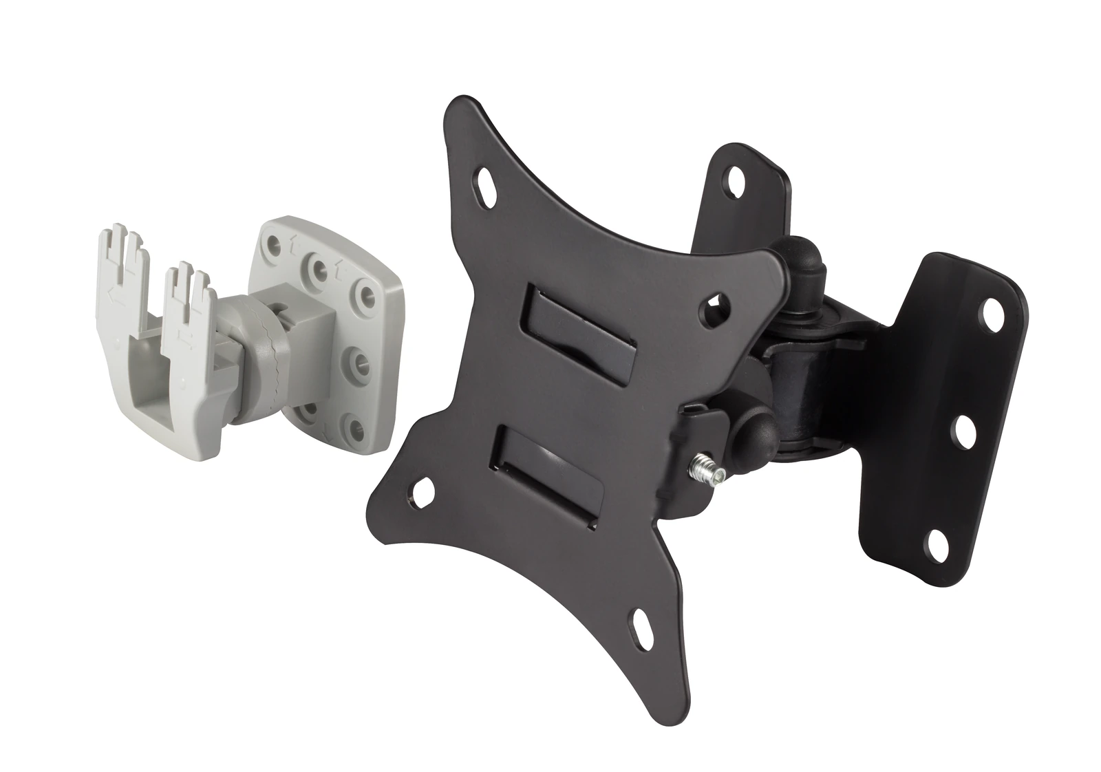
mounting surface, spacing, tilt, and enclosure rating
connector, cable length, bend radius, and routing
reader port power and permitted configuration
A higher peak gain often accompanies a narrower beam and may increase reads beyond the intended zone. A wider pattern can improve coverage while increasing overlap with adjacent zones. Compare the pattern and installed read results against the required geometry.
| Deployment Item | Requirement to Define | Selection or Verification Record |
|---|---|---|
| Regional band | Intended country or countries, applicable equipment band, and channel conditions | Controlled regional configuration for the reader, antenna, and finished equipment |
| Reader configuration | Reader model, firmware, regional setting, port power, number of active ports, and operating mode | Configuration export or test record tied to the validated hardware revision |
| Polarization | Expected tag orientations and whether linear or circular operation fits the read zone | Polarization evidence plus representative orientation tests |
| Beam and read zone | Desired coverage, exclusion zones, travel direction, speed, height, and overlap between antennas | Pattern context and an installed read-zone map showing successful and unwanted reads |
| Cable loss | Cable type, length, connector transitions, routing, and allowed loss | Assembly data and end-to-end loss or power-budget record |
| Mounting | Position, tilt, spacing, fasteners, ground, enclosure, and maintenance tolerance | Revision-controlled installation drawing and repeatability check |
| Nearby materials | Metal, liquid, walls, floor, machinery, products, people, and other antennas | Site survey and tests with representative materials and operating states present |
| Desired reads | Tag types, attachment, orientation, population, movement, and minimum acceptance outcome | Recorded test matrix using production-intent tagged items |
| Unwanted reads | Locations, items, or adjacent zones that must remain excluded | Negative test results at representative reader settings and site conditions |
| Compliance and change control | Responsible economic operator, assessed configuration, documentation, and changes that may affect conformity | Approved compliance plan and revalidation rules for antenna, cable, power, firmware, enclosure, or installation changes |
Treat compliance as a finished-equipment task
The European Commission Radio Equipment Directive overview states essential requirements concerning safety and health, electromagnetic compatibility, and efficient use of radio spectrum. The actual obligations depend on the radio equipment placed on the market, its intended use, configuration, and applicable standards.
The finished radio-equipment manufacturer is responsible for its applicable conformity assessment, technical documentation, declarations, and labeling. The antenna supplier provides component data, while the reader manufacturer or integrator controls and validates antenna and software configurations. Changing antenna gain, cable loss, reader power, firmware, or enclosure may affect the assessed configuration and should enter change control.
Validate representative tagged items
Validate UHF RFID antenna selection with a test matrix covering tag type, attachment material, orientation, distance, movement, stack or population, and environmental state. Record reader model, firmware, regional configuration, port power, cable, antenna position, and surrounding structures. Test both desired reads and exclusion zones.
Repeat tests after production-intent installation. Surveying an empty site or holding a tag in the best orientation is not an acceptance test. Preserve raw results and define what variation is allowed between sites or assembly lots.
Frequently asked questions
Can one antenna SKU(Stock Keeping Unit?) be used throughout Europe? Possibly, but only after checking its band, reader configuration, installation, and the finished-equipment compliance plan for each intended market.
Is circular polarization always preferable? No. It can help with varied tag orientation, while linear polarization may be efficient when orientation is controlled. Validate the actual read zone.
Does ETSI compliance guarantee application performance? No. A regulatory test and an operational read-zone test answer different questions.
Use RF technology insights, RF antenna and component resources, and the applications hub for adjacent planning.
Review UHF RFID antenna selection for a European application.
References
GS1 EPC UHF Gen2 Air Interface Protocol
ETSI EN 302 208 V3.4.1
European Commission — Radio Equipment Directive
https://www.gs1.org/standards/rfid/uhf-air-interface-protocol
https://www.etsi.org/deliver/etsi_EN/302200_302299/302208/03.04.01_60/en_302208v030401p.pdf
Related reading
RFID Reader Antenna Manufacturer Selection Guide for European OEMs