
An RFID antenna datasheet answers a set of different questions: which frequencies the antenna supports, how it radiates or couples energy, how it connects to the reader, and how it fits into an assembly. Read the units, qualifiers, and test conditions with each value. A typical value measured in one configuration is not automatically an acceptance limit for another.
Start with the application and document revision
Identify the part number, document date, operating region, and intended reader interface. Distinguish a reader antenna from a passive tag antenna and a near-field application from a far-field one. These distinctions change which fields deserve the most attention.
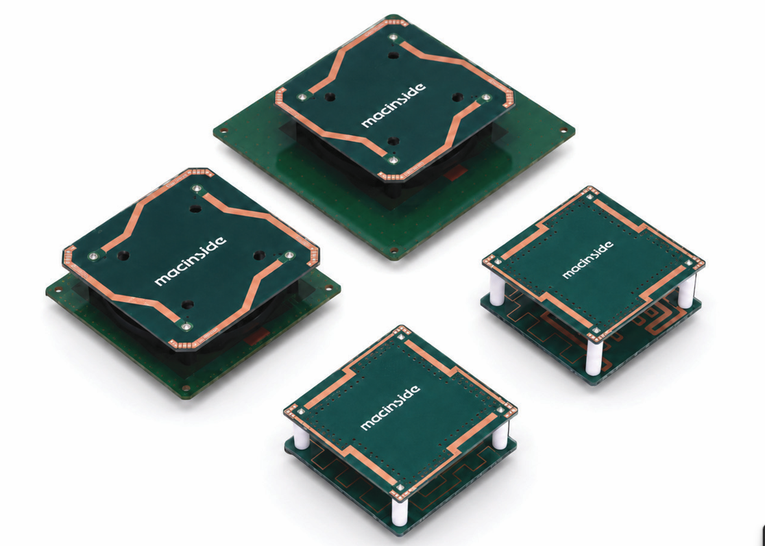
For a portal, the coverage pattern and tag orientation may drive selection. At a controlled desktop station, unwanted reads outside the presentation area may be just as important as reads inside it. The same datasheet cannot resolve both workflows without application testing.
Read the fields as engineering questions
| Field | How to interpret it | Question to resolve |
|---|---|---|
| Frequency range | The interval for which operation is specified | Does the released part cover the required regional channels? |
| Bandwidth | An interval defined by a criterion, such as a reflection limit | What criterion and measurement configuration define the interval? |
| Gain and pattern | Directional 및 이득 with stated frequency and polarization | Is the useful field present across the required angles? |
| Beamwidth | Angular width measured at a stated level and in a stated plane | Is the specified plane the one relevant to the installation? |
| Polarization and axial ratio | Field orientation and, for circular polarization, departure from the ideal circular state | Does it suit the expected tag orientations across the band and read zone? |
| VSWR or return loss | Reflection at the stated feed reference plane | Were the intended cable, fixture, and mounting conditions used? |
| Weight and dimensions | Mechanical information for a defined part or assembly | Are the ground, housing, connector, and cable included? |
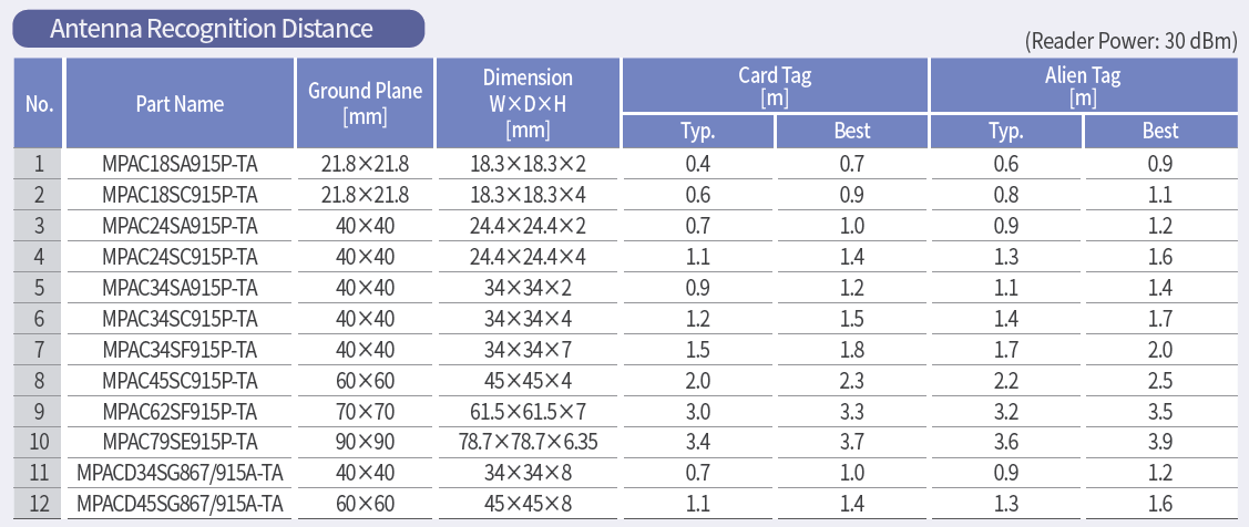
| Read distance | A system observation dependent on reader, tag, orientation, and surroundings | Can the reported setup be reproduced for this application? |
For a comparable setup, a VSWR closer to 1:1 indicates less reflection. A higher positive return-loss value also indicates less reflection. Neither number measures radiation efficiency. A lossy assembly can absorb power while showing a good input match.
Work through a company catalogue example
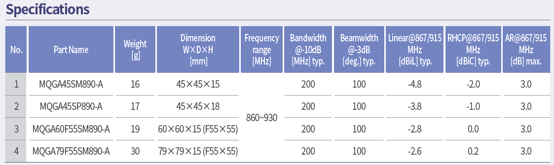
The July 2026 MAC technologies Inc. catalogue lists the following entries for the QGA part MQGA45SM890-A on printed page 12.
| Catalogue field | Published entry | What it establishes |
|---|---|---|
| Antenna weight | 16 g | The listed antenna weight; confirm assembly inclusions |
| Dimensions | 45 × 45 × 15 mm | The listed mechanical envelope |
| Frequency range | 860–930 MHz | The catalogue range; regional equipment rules still apply |
| Beamwidth at −3 dB | 100°, typical | An angular value under the catalogue conditions; request the relevant pattern planes |
| Axial ratio | 3.0 dB maximum | A polarization-related limit; confirm its frequency and angular scope |
| 이득 | -2.0 dBiC | 카탈로그 조건의 주파수에서의 이득 |
The catalogue identifies the antenna table as company chamber data. The supplied QGA.xlsx sheet adds an RHCP gain of -2 dBiC typical and an axial ratio of 3 dB maximum at 867/915 MHz for MQGA45SM890-A. Preserve those frequencies and qualifiers when comparing parts, and request the pattern planes and mounting conditions for the intended installation.
Named model specification example
| MQGA45SM890-A | Value in the supplied QGA sheet |
|---|---|
| Antenna weight | 16 g |
| Dimensions W × D × H | 45 × 45 × 15 mm |
| Frequency range | 860–930 MHz |
| RHCP gain at 867/915 MHz | −2 dBiC typical |
| Axial ratio at 867/915 MHz | 3 dB maximum |
Source: QGA.xlsx, Gain table, column headers in row 4 and model data in row 6. These are source-sheet values, not measurements of an unidentified product photograph.
Keep typical, maximum, and tested values separate
A typical value describes expected behavior under the stated conditions. A maximum or minimum defines a limit only within its stated scope. A measured value describes the identified sample and test. Preserve these labels when transferring data into a procurement spreadsheet.
Also keep polarization references with gain values. A catalogue may distinguish linear and circularly polarized measurements. Do not combine those entries into a single ranking without understanding the measurement convention.
Finish with a comparison and test plan
Record which requirements are supported by the datasheet and which need clarification. Request missing cable, environmental, or tolerance information. Then test the production-intent reader, antenna, cable, enclosure, representative tags, and mounting state together, including locations where reads must be rejected.
For a datasheet review with MAC technologies Inc., provide the exact part and document revision, required band, reader configuration, mechanical drawing, intended tag presentation, and the acceptance questions that remain open.
References
MAC technologies Inc. catalogue, July 2026, printed pages 10–13. Product examples and their listed weights, dimensions and RF fields are historical catalogue data; confirm the current drawing and specification before ordering.
GS1 EPC UHF Gen2 Air Interface Protocol
IEEE 149-2021 — IEEE Recommended Practice for Antenna Measurements
https://www.gs1.org/standards/rfid/uhf-air-interface-protocol
https://standards.ieee.org/ieee/149/6667/
Related reading
RFID Antenna Specifications: A Selection Guide