
Metal near an RFID antenna can change its impedance and reshape the surrounding field. Metal can also affect the tag attached to an item. Treat these as related but separate integration questions: an antenna may retain an acceptable feed match while the system develops missed reads or unwanted reads because the tag, reflections, or presentation geometry changed.
Describe the conductive surroundings
Start with a drawing or photographs of the installation. Mark the mounting surface, antenna orientation, nearby walls and guards, conveyor or shelf, cable route, enclosure, and the positions of the tagged items. Include moving doors and service positions if they change the operating geometry.
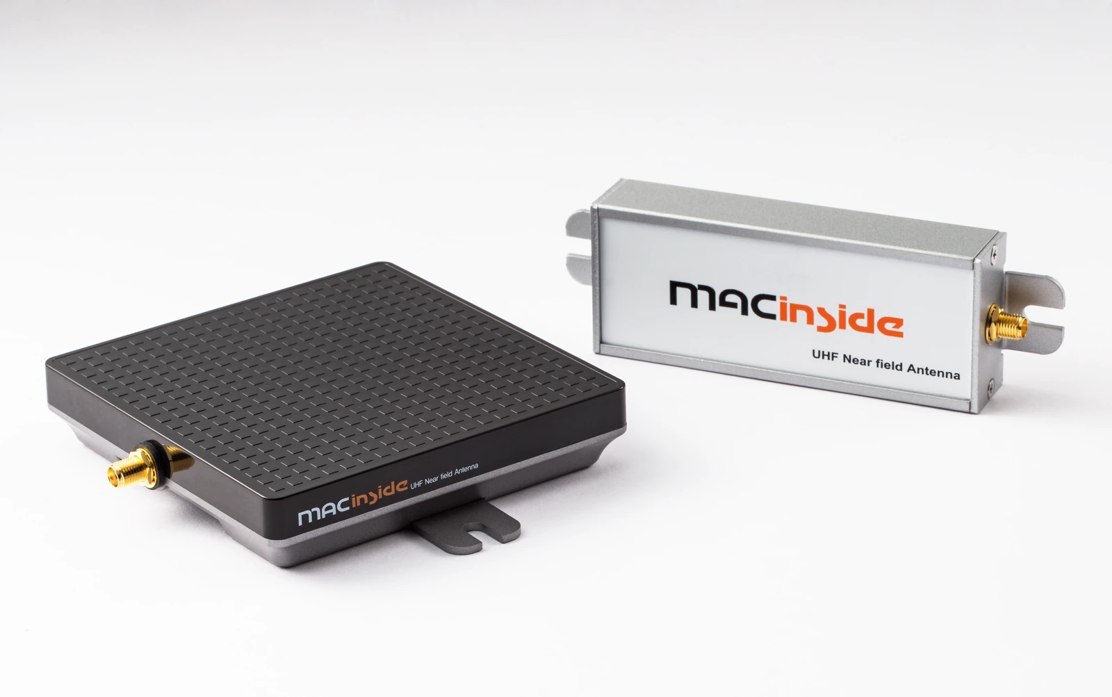
Record surface material, dimensions, coatings, joints, and nominal clearance. There is no universal safe spacing that applies to every antenna, mounting arrangement, and tagged item. An antenna designed to use a ground plane can behave differently from a structure designed for another boundary.
Distinguish the possible causes
| Observation | Possible explanation to investigate | Useful next check |
|---|---|---|
| Input reflection changes after mounting | Antenna loading, feed change, cable movement, or fixture difference | Repeat the feed measurement with controlled cables and clearance |
| Feed behavior is stable but reads change | Tag loading, reflections, orientation, reader settings, or a changed field pattern | Repeat the tagged-item trial with those variables recorded |
| Objects outside the intended area are read | Reflections, power setting, antenna placement, or timing | Test an explicit unwanted-read route |
| Performance changes after maintenance | Different bracket position, cable route, enclosure state, or nearby structure | Compare the as-built installation with the accepted drawing |
These observations guide investigation; they do not identify a cause by themselves. Preserve the baseline before changing the antenna or adding shielding.
Run a controlled mounting trial
Begin with a repeatable reference configuration. Then vary clearance, bracket position, or orientation one at a time while keeping the reader settings, tags, route, and measurement procedure fixed. Use the production-intent cable and enclosure as early as practical.
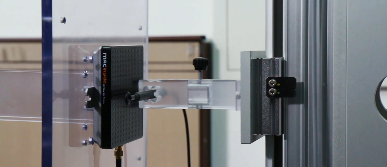
Measure feed behavior and application behavior separately. The feed result helps identify changes at the antenna port. The application result shows whether representative items are read at the required positions and speeds. For a metal-mounted tag, verify that the selected tag is intended for that host material rather than assuming a reader-antenna change will solve the problem.
Check the whole read zone
Use representative loaded and unloaded conditions where both occur in service. Test expected tag orientations, the nearest and farthest required positions, and adjacent areas that must remain excluded. Record successful reads, missed reads, and unwanted reads with the same reader power and timing settings.
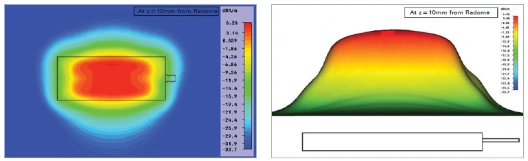
If a conductive cover or shield is proposed, include it in the trial and verify the complete zone again. It may change both the desired field and the areas where reads are lost. GS1 TIPP provides tagged-item test context; the actual installation still needs its own configuration and acceptance criteria.
Release an installation that can be restored
The approved record should identify bracket position, clearance tolerance, fasteners, cable routing, enclosure state, reader configuration, representative tags, and the acceptance route. State which checks repeat after relocation, repair, or a change in nearby metal.
For a metal-environment review with MAC technologies Inc., send the mounting drawing, conductive surface details, tag and reader information, required read zone, and observations from a controlled trial. Include the clearance and mounting states that produced each result.
References
GS1 TIPP RFID test methodology
IEEE 149-2021 — IEEE Recommended Practice for Antenna Measurements
https://www.gs1.org/standards/epc-rfid/tipp
https://standards.ieee.org/ieee/149/6667/
Related reading
RFID Antennas for Gate and Portal Systems