
Define the installed height and mass limits
Low-profile and lightweight antennas are attractive when a platform has limited clearance, mass budget, or service space. The engineering question is not whether lighter is always better. It is whether the proposed assembly meets the RF, mechanical, thermal, environmental, and maintenance requirements at the same time. Freeze the platform boundary before comparing candidate designs.
Record the available height, footprint, allowable mass, mounting plane, nearby conductive structures, radome or cover, cable route, connector access, and expected orientation. A profile that looks small in isolation may require a bracket, counterweight, or larger ground structure that changes the system tradeoff.

Separate profile from mass and performance
Profile and mass are related but not interchangeable. A thinner construction can require loading, a different substrate, a larger ground, or tighter mechanical tolerances. A lighter assembly can change stiffness, vibration response, thermal paths, or connector support. Compare each property against the operating condition rather than using a single “compact” label.
| Tradeoff | What to record | Why it belongs in the decision |
|---|---|---|
| Profile | height, clearance, cover, keep-out | determines platform fit and coupling |
| Mass | antenna, bracket, cable, fasteners | shows the complete installed load |
| RF behavior | band, bandwidth, efficiency, pattern, polarization | connects geometry to system need |
| Integration | ground, loading, cable, service access | exposes installation sensitivity |
Use a common configuration for the comparison. Do not compare a bare antenna measurement with an installed candidate that includes a radome, bracket, or cable.
Examine bandwidth and efficiency together
A low-profile structure may depend more strongly on ground, loading, or tuning than a larger free-space structure. Ask how bandwidth is defined, where the reference plane is, and whether efficiency or pattern is measured in the installed boundary. If a design uses matching networks or lossy loading, record the consequence instead of treating it as an invisible detail.

IEEE 149-2021 provides recommended practice for antenna measurements, but it does not define the acceptance limit for a specific platform. The project should specify frequency points, polarization reference, fixture, cable, environment, and repeatability expectations.
Include SWaP and platform integration
Size, weight and power (SWaP) planning should include the antenna, bracket, connector, cable, protective cover, required ground structure, and any powered antenna electronics. Review thermal expansion, fastener access, sealing, cleaning, and repair actions. Evaluate the complete installed assembly when comparing alternatives.
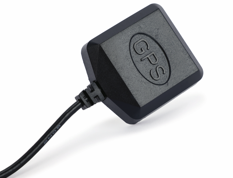
Make the platform owner identify the condition that matters most: clearance, mass, field of view, efficiency, service time, or a combination. Use that priority to weight the trade study without claiming a universal winner.
Plan environmental and mechanical validation
Tailor environmental checks to the actual platform life cycle. The DLA ASSIST record for MIL-STD-810 describes an environmental tailoring process rather than a blanket design or test specification. Use it as context for deciding relevant exposures, fixtures, sequence, and post-test comparisons; do not describe a design as certified merely because the standard is referenced.
Define the pre-test RF baseline, assembly revision, environmental exposure, post-test RF comparison, visual inspection, and acceptance criteria. Vibration, temperature, moisture, dust, or handling can affect the antenna, feed, cover, and mounting interface differently.
Make the buyer comparison repeatable
For a review with MAC technologies Inc., send the installed height and mass limits, platform drawing, mounting and ground conditions, cable and connector details, environmental plan, and required RF evidence.
RF technology insights provides related background, while RF antenna and component resources and the applications hub support the next engineering review.
Record the tradeoff, not just the winner
Record the alternatives considered, the constraint driving the choice, and the evidence needed for acceptance. Review the affected RF and mechanical requirements if the platform envelope or mounting plane changes.
Add a sensitivity review for the variables most likely to move during installation. Clearance, fastener torque, cover thickness, cable bend, ground continuity, and surface finish can change the local RF boundary. Record the nominal condition and the credible tolerance, then decide whether the tolerance belongs in the drawing, the installation instruction, or the validation plan.
The trade study should also show the service consequence of each option. Note how a technician reaches the connector, removes a cover, replaces a cable, or checks the mount without disturbing the accepted orientation. A lighter or thinner antenna can be a poor platform choice when it requires fragile support or creates an unrepeatable field adjustment. Keep those observations beside the RF evidence so the buyer can see the full system decision.
Also distinguish a design change from an installation correction. If a technician can restore the approved position with a defined shim or torque value, document that control. If the correction changes the feed, ground, or cover, route it through engineering review instead of treating it as routine service. The distinction protects both the RF baseline and the platform maintenance plan.
References
IEEE 149-2021 — IEEE Recommended Practice for Antenna Measurements
MIL-STD-810 — Environmental Engineering Considerations and Laboratory Tests
https://standards.ieee.org/ieee/149/6667/
https://quicksearch.dla.mil/qsDocDetails.aspx?ident_number=35978