
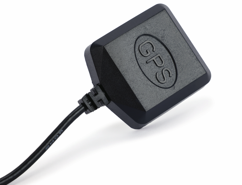
GPS/GNSS antennas provide a signal interface to a navigation or timing receiver. In a tactical communication system, their role should be distinguished from the antenna carrying the communication link. Define the required satellite signals, receiver architecture, platform placement, interference environment, and verification method before selecting the GNSS antenna assembly.
Match signals and interfaces across the receive chain
List the constellations and bands required by the receiver. Check that the antenna, filter, amplifier, cable, and receiver support the same signal plan. GPS.gov interface documents describe the transmitted GPS signal interfaces; they do not establish a particular antenna’s installed performance.

Compare passive elements and active assemblies against the receiver requirements. Confirm the supported signals and bands from the selected model’s data, then define any filtering, amplification, bias and cable interfaces.
| Architecture | Interface information needed | Integration question |
|---|---|---|
| Passive antenna | Band, polarization, feed, cable, receiver noise assumptions | Where are filtering and amplification provided? |
| Active antenna | RF data plus bias voltage, current, gain, noise contribution, protection | Does the powered antenna chain suit the receiver and cable? |
| Complete installed chain | Antenna, filter, amplifier, cable, receiver, placement | Does the system meet its navigation or timing requirement in the intended environment? |
Place the antenna for the required sky view
Record the mounting surface, ground relationship, radome, nearby structures, other antennas, and platform orientations. Obstructions can restrict satellite visibility, while reflective surfaces can introduce multipath. A location that works on an open fixture may behave differently on the platform.
Include the cable and connector in the drawing. State length, loss, routing, strain relief, and sealing. For an active antenna, verify the supply and fault behavior at the antenna interface as well as the receiver connection.

Review interference as a system condition
Map nearby transmitters, clocks, switching electronics, and the operating modes that may affect the receive chain. Filtering, front-end linearity, antenna placement, cable coupling, and receiver behavior all contribute to the result. An antenna bandwidth or gain value alone cannot establish resilience against interference.
Define which checks use a cable interface, radiated signals, or the installed platform. An adaptive multi-element architecture adds channel, processing, calibration, and test requirements beyond the conventional passive and active antennas discussed here.
Separate component checks from receiver observations
Begin with sample identity, connector and cable inspection, bias checks where relevant, and the agreed feed measurements. Then evaluate the receive chain using the controlled signal and platform conditions. Keep sky view, blockage, interference state, receiver firmware, and acceptance criteria with each observation.
If a cable or filter changes, revisit the receive-chain boundary before interpreting a navigation change. Compare the same assembly revision and environmental state, and retain the raw data or test record needed to explain the result.
For a GNSS antenna discussion with MAC technologies Inc., provide the target signals, receiver configuration, platform drawing, cable and bias interfaces, interference assumptions, and required verification outputs. This lets the review distinguish antenna selection from the performance of the complete navigation or timing system.
References
GPS.gov Interface Control Documents
GPS.gov Technical Documentation
https://www.gps.gov/interface-control-documents-icds-interface-specifications-iss
https://www.gps.gov/technical-documentation