
Military GNSS antenna design begins with the navigation signals, receiver chain, platform installation, interference environment, and service conditions. Define the required bands, polarization, gain coverage, filtering, cable loss, grounding, sealing, and environmental tests. Evaluate these requirements together in the integrated system.
Select the architecture before specifying the antenna
A conventional passive GNSS antenna is a radiating element connected to a receiver chain that supplies any required filtering, gain, biasing, and protection elsewhere. An active GNSS antenna chain places a low-noise amplifier and often filtering close to the antenna; the interface must then define bias voltage, current, gain range, noise contribution, cable loss, protection, and fault behavior as well as RF coverage.
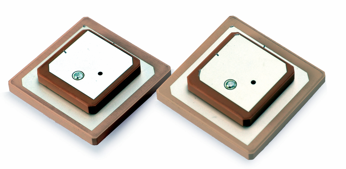
A fixed-reception-pattern antenna (FRPA) has a pattern established primarily by its physical antenna structure and installation. It may be appropriate when the required sky coverage and interference environment can be addressed without adaptive spatial processing. A controlled-reception-pattern antenna (CRPA) is a multi-element system concept used with suitable receiver or antenna electronics to control the composite reception pattern. It adds element, channel, calibration, processing, interface, test, size, weight, power, and integration requirements; the term alone is not evidence of anti-jam performance.
Safran’s CRPA testing guide describes the additional channel and test requirements of multi-element systems. MAC technologies Inc. product examples in this article are conventional antenna elements; a CRPA requirement needs a separate system architecture and evidence package.
Define the signals and receiver interfaces
List each required navigation signal and check that the antenna, filter, low-noise amplifier, bias network, cable, and receiver support the same plan. GPS.gov publishes the official interface specifications for civil GPS signals on L1, L2, and L5. Use the relevant signal requirements when defining the receive chain.
The interface control document should state:
required GNSS constellations, signals, and frequency bands
passive or active antenna architecture and receiver noise assumptions
nominal impedance, connector, cable type, length, and allowable loss
polarization and gain coverage over the required elevation angles
supply voltage, current, protection, and fault behavior for active electronics
out-of-band rejection and coexistence requirements
Treat interference as a system problem
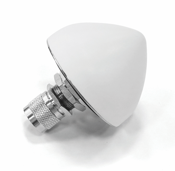
GNSS signals arrive at low power, so antenna placement, platform transmitters, clocks, digital electronics, and external emitters deserve an interference budget. The official GPS.gov spectrum and interference overview identifies adjacent-band emissions, intentional or unintentional jamming, and space weather among interference sources.
A military GNSS antenna design review should map every platform transmitter and harmonic that can couple into the antenna, cable, amplifier, or receiver. Define blocking, recovery, intermodulation, and desensitization tests where relevant. Filtering may improve rejection but can add insertion loss or group-delay effects, so the antenna, filter, amplifier, and receiver should be reviewed as one chain.
Recognize when a conventional architecture may be insufficient
Escalate the architecture decision when the required evidence cannot be closed by antenna placement, a fixed pattern, filtering, receiver tolerance, or platform-level electromagnetic compatibility work. The decision should begin with the actual interference and resilience requirement, not with a preference for a named antenna class.
Interference environment: identify expected in-band and out-of-band emitters, intentional and unintentional cases, duration, direction, level assumptions, and recovery requirements.
Platform transmitter coupling: map onboard radios, harmonics, clocks, switching electronics, cable routes, antenna separation, and simultaneous operating modes.
Sky-view constraints: record blockage, multipath surfaces, platform attitude, antenna location, and the elevation region required by the navigation or timing function.
Receiver-chain requirements: define supported bands and constellations, front-end linearity, filtering, gain, dynamic range, bias, channel count, and any processing interface.
SWaP constraints: allocate size, weight, power, cooling, cabling, connector count, mounting volume, and maintenance access at system level.
Resilience requirements: state the continuity, integrity, recovery, and verification outcomes required from the complete PNT system without assuming that one antenna component can provide them.
If these questions lead to a multi-element or adaptive architecture, the project needs corresponding calibration, synchronization, processing, simulation, radiative testing, and platform-integration evidence. If they do not, a well-integrated conventional or active GNSS antenna chain may avoid unnecessary complexity.
Engineer the installation and environment
The installation drawing should define the platform surface, ground plane, radome, fasteners, cable route, seals, nearby antennas, and field of view. Check sky coverage, multipath, and shadowing at the intended mounting location. Control dimensions and materials that affect RF behavior.
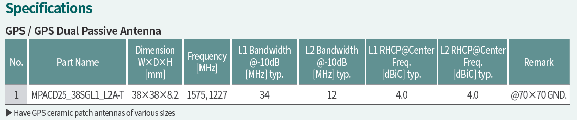
Environmental requirements should be tailored to the actual life-cycle profile. The official MIL-STD-810 record explains that the standard provides an environmental tailoring process rather than imposing universal design or test specifications. Select temperature, vibration, shock, humidity, salt, dust, altitude, or other methods only when the platform profile justifies them.
| Requirement Area | Questions to Define | Evidence or Test Needed |
|---|---|---|
| Signals and bands | Which constellations and signals are required, and which combinations must operate simultaneously? | Controlled interface requirements and band-specific antenna or chain evidence |
| Antenna and receiver interface | Passive or active chain, impedance, connector, cable loss, bias, gain, noise, protection, and fault behavior? | Interface drawing, component data, calibrated RF measurements, and end-to-end receiver checks |
| Filter and LNA chain | What rejection, gain, noise, linearity, group-delay, power, and temperature behavior is required? | Cascaded analysis plus measured chain data at defined levels, temperatures, and reference planes |
| Interference | Which onboard and external emitters, coupling paths, operating modes, and recovery cases are credible? | Interference-control plan, susceptibility or coexistence tests, and documented receiver recovery behavior |
| Platform installation | What sky view, ground plane, radome, cable route, separation, mounting, and maintenance limits apply? | Installation drawing, platform survey, pattern or coverage evidence, and integrated functional test |
| Environment | Which transport, storage, operating, vibration, shock, temperature, moisture, or other exposures follow from the life-cycle profile? | Tailored test plan, representative hardware, pre- and post-exposure RF and functional checks |
| Verification | Which component, chain, simulated, radiative, and platform tests close each requirement? | Traceable verification matrix with configuration, calibration, sample, raw data, and pass/fail records |
Validate from component to platform
Validation for military GNSS antenna design should use staged evidence: component inspection, calibrated impedance measurement, antenna-pattern or gain testing, active-chain checks, environmental exposure, and integrated receiver performance. IEEE 149-2021 provides recommended antenna measurement practices, but the project must still define fixtures, uncertainty, preconditioning, sample count, and pass/fail criteria.
After environmental tests, repeat the RF and functional checks that could reveal connector, seal, cable, tuning, or amplifier damage. Preserve serial numbers, hardware and software revisions, calibration state, and raw results.
Frequently asked questions
Does citing MIL-STD-810 prove qualification? No. Qualification requires an approved tailored test plan, representative hardware, completed testing, and attributable results.
Should more GNSS bands always be added? Not automatically. Each band affects antenna bandwidth, filtering, receiver architecture, size, loss, and verification scope.
Can an antenna datasheet establish platform performance? No. Installation, cable, interference, receiver design, sky view, and multipath remain system variables.
See RF technology insights, RF antenna and component resources, and the applications hub for related context.
Discuss a GNSS antenna requirement with an engineering team.
References
Safran — An Engineer’s Guide to CRPA Testing (architecture and test context; not evidence of MAC product capability).
https://safran-navigation-timing.com/an-engineers-guide-to-crpa-testing/
GPS.gov — Interface Control Documents and Interface Specifications
GPS.gov — Spectrum and Interference Issues
MIL-STD-810 — Environmental Engineering Considerations and Laboratory Tests
IEEE 149-2021 — IEEE Recommended Practice for Antenna Measurements
https://www.gps.gov/interface-control-documents-icds-interface-specifications-iss
https://www.gps.gov/spectrum-interference-issues
Related reading
GPS/GNSS Antenna Solutions for Tactical Communication Systems