
RF diplexer development combines two frequency-selective branches around a common port so that the intended bands can share part of an RF path. The result depends on the branch filters, shared junction, terminations, connectors, enclosure, and test reference planes. Treating each branch independently can miss interactions that appear only when the complete network is assembled.
Define the common port and both branches
Create an unambiguous port map before discussing topology. Identify the common port, low-band or first branch, high-band or second branch, signal direction, impedance, connector interface, and termination condition. The same port names should appear in the requirement matrix, schematic, drawing, simulation, test file, and production work instruction.
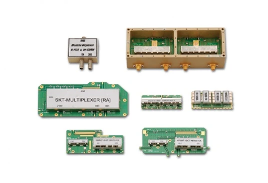
Ports and frequency paths
| Item | Typical two-port filter | Typical passive diplexer |
|---|---|---|
| Ports | Port 1 and port 2 | Common C, branch A and branch B |
| Frequency path | One frequency-selective transmission path | C to A in band A; C to B in band B |
| Direction | Reciprocal passive devices can be used in either direction | Separates or combines the two bands in a reciprocal network |
| Verification | Transmission, reflection and rejection | Both branch paths, all port matches and branch isolation |
C, A and B are explanatory port labels. Use the device drawing for actual numbering, and terminate unused ports as required by the measurement method.
Define passband edges, stopband regions, and guard band. A small separation between bands can increase the difficulty of achieving low insertion loss and high isolation at the same time. Also identify source and load behavior because a branch that is not terminated as assumed can alter the common-port response.
Translate system needs into measurable limits
Insertion loss affects the wanted signal. Return loss describes how well each port is matched under the stated conditions. Branch-to-branch isolation indicates unwanted coupling, while rejection identifies attenuation in specified frequency regions. These values should be expressed over frequency ranges rather than as isolated best-case points.
Power conditions matter when the application requires them, but they must be defined rather than inferred. State continuous or peak power, duty cycle, waveform context, temperature, and expected mismatch. Do not assume that a small-signal S-parameter result proves high-power behavior.
| Requirement | Define at the start | Evidence at review |
|---|---|---|
| Port match | port, band, reference plane, limit | S11, S22, and S33 as applicable |
| Insertion loss | path, passband, conditions | transmission trace for each branch |
| Isolation | source and measured branch, termination | branch-to-branch S-parameter |
| Rejection | blocked band and attenuation limit | full sweep with limit lines |
Select topology around the complete network
The branch filters and shared junction should be developed together. Depending on the bands and constraints, the design may use lumped, distributed, ceramic, cavity, waveguide, or mixed structures. The choice affects size, Q, loss, power handling, tolerance, assembly, and test access. No topology is automatically superior outside a defined application.
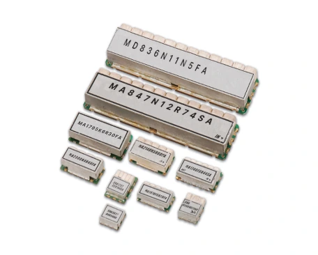
Simulation should include the common path, branch interaction, connector transitions, grounding, enclosure, and production-intent materials where practical. Sensitivity analysis can reveal which resonators, coupling gaps, substrate properties, or assembly dimensions require tighter control.
Build prototypes that preserve port identity
Release a controlled schematic or layout, mechanical drawing, BOM, port map, and assembly revision for each prototype. Mark physical ports clearly and use the same cable and termination conventions during comparison. If tuning changes are made, retain a before-and-after record instead of relying on an undocumented bench state.
Production-intent connectors, housing, grounding, fasteners, and thermal paths should be introduced before final correlation. These details can change loss, resonance, isolation, and repeatability even when the branch circuits are unchanged.
Verify every S-parameter path
Use a calibrated multi-port VNA, or a suitable sequential two-port method, to measure transmission, reflection and branch coupling. For standard S-parameters, terminate the ports not being driven in the measurement reference impedance, including any unused port in a sequential setup. Evaluate installed mismatch conditions separately.
The test record should state calibration, reference plane, sweep range, point count or resolution, power, averaging, cables, adapters, fixture, temperature, and all unused-port terminations. Measure each branch from the common port, return loss at every relevant port, and branch-to-branch isolation. A branch-only result is incomplete because it excludes the shared network and the termination dependency.
Correlate prototype results and investigate deviations
When simulation and measurement differ, examine reference-plane placement, connector launches, material tolerance, parasitics, enclosure contact, grounding, and termination state before changing the core topology. Use repeat builds to distinguish a model gap from sample-specific variation.
Record deviations against the applicable requirement and retain raw Touchstone or equivalent data with sample and revision identity. A plot pasted into a report is useful for review, but it should not be the only retained evidence.
Transfer the design into controlled production
Production release should connect critical geometry and material controls to an inspection method and RF test. Define which paths are checked, which limits apply, how fixtures are verified, and how reference units or correlation samples are managed. RF diplexer development is ready for release only when the shared port and both branches remain traceable to the approved multi-port evidence. Establish rules for retest when a connector, material, housing, supplier, assembly process, or termination condition changes.
For a diplexer review with MAC technologies Inc., provide the port map, band plan, insertion loss, return loss, isolation and rejection limits, power conditions, mechanical envelope, connector definitions, and required test data.
References
Keysight — Scalar Network Analyzer: Migrating from Scalar to Vector Network Analyzer Systems, “Filters and Frequency Selective Devices,” pp. 13–15.
https://www.keysight.com/ie/en/assets/7018-02338/technical-overviews/5990-4798.pdf
Three-port measurement context: Rohde & Schwarz, 3-Port Measurements, https://cdn.rohde-schwarz.com/pws/dl_downloads/dl_application/application_notes/1ez26/1ez26_1e.pdf