
Custom antenna design uses 2D drawings, 3D models, simulation, and measurements for different purposes. The drawing defines what will be manufactured and inspected. The model represents geometry and material assumptions. RF measurements establish how an identified physical sample behaves under stated conditions. Keep their revisions connected as the design develops.
Give each file a clear job
| Record | Information it should contain | How it is used |
|---|---|---|
| 2D drawing | Dimensions, tolerances, datums, materials, interfaces, notes | Manufacturing and inspection |
| 3D model | Geometry, stack-up, host features, clearances, assembly relationships | Packaging and simulation input |
| RF model | Ports, materials, boundaries, feed, ground, represented surroundings | Evaluate design options and sensitivity |
| Prototype record | Drawing and BOM revision, sample identity, substitutions, tuning changes | Explain the tested hardware |
| Test and release record | Setup, raw data, acceptance decision, released revisions | Handoff and later comparison |
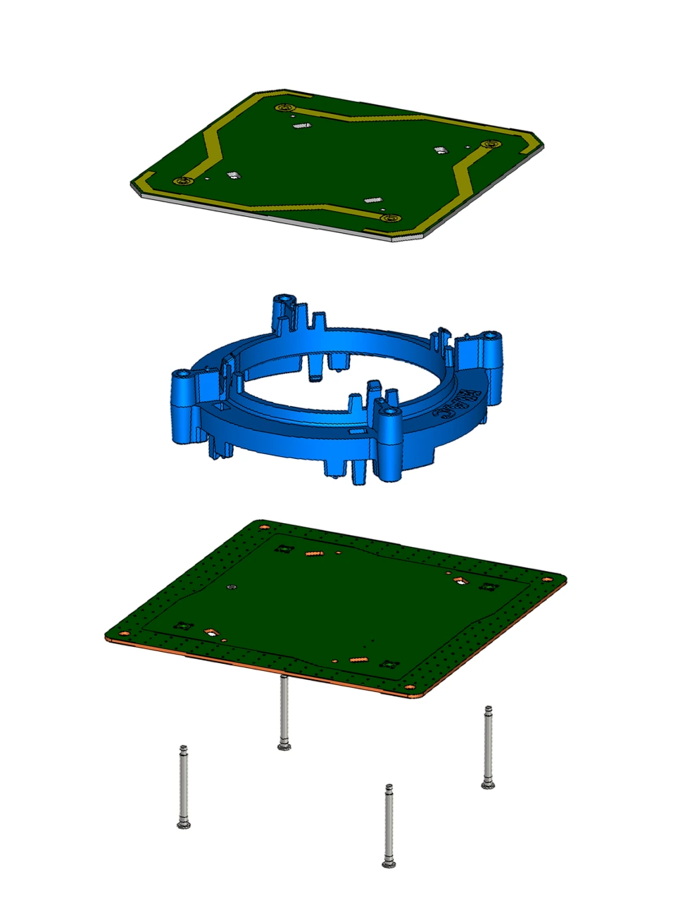
The company’s exploded CAD illustration separates the boards, supports and fasteners. Use the assembly relationships to identify controlled dimensions, then add the tolerances, materials and inspection notes needed in a released manufacturing drawing.
Define the installed geometry before tuning
Place the feed, ground, connector, cable exit, housing, adhesive, fasteners, and nearby conductive parts in the design view. Identify the available volume and the dimensions that may affect resonance, matching, pattern, or assembly repeatability.
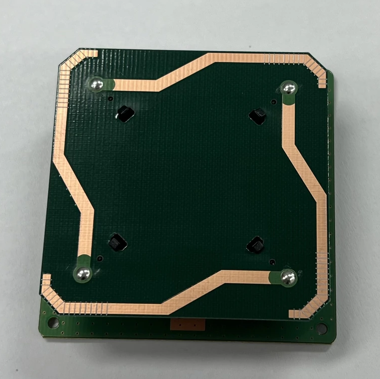
A nominal outline alone may be insufficient. For example, changing the spacing between a radiator and a nearby housing surface can alter the electromagnetic environment even when the external dimensions remain the same. Record that spacing and its tolerance if it matters to the selected design.
Use simulation to choose the next physical check
Document material values, geometry revision, ports, and the surrounding structures represented in the model. Vary plausible dimensions or material properties to identify sensitive features. The aim is to decide which tolerances need control and which prototype measurements will test the design assumptions.
Keep predictions separate from measured results. A simulation can guide a feed-position or matching-network change, but the final assembly still needs physical correlation.
Correlate the prototype with the model
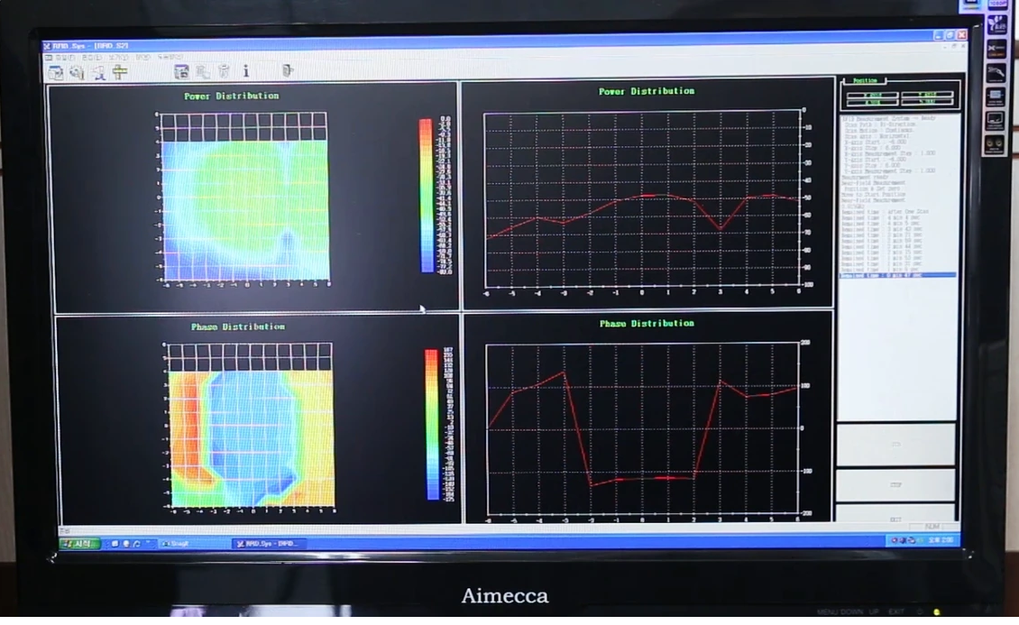
Identify temporary cables, connectors, fixtures, and material substitutions before measuring. Use a defined calibration and reference plane for feed measurements. For radiation measurements, record orientation, mounting, cables, environment, and the applicable method.
When model and measurement differ, compare the configurations before adjusting the design. Material tolerance, adhesive, connector representation, cable routing, or an omitted nearby part may explain the difference. Capture each tuning change and its effect so the accepted state can be reproduced on another build.
Release a consistent drawing and evidence package
Confirm that the approved 2D drawing, 3D model, BOM, sample identifier, and test record describe the same assembly. Include inspection points, acceptance limits, allowed substitutions, and the changes that require renewed RF or mechanical review.
Complete the design handoff with process controls, sampling decisions, and manufacturing records. The related simulation-to-production guide covers those release activities.
For a custom design review with MAC technologies Inc., provide the available CAD, mechanical envelope, materials, mounting and feed assumptions, RF targets, prototype state, and expected release documents.
References
IEEE 149-2021 Recommended Practice for Antenna Measurements
https://standards.ieee.org/ieee/149/6667/