
Panel and omnidirectional antennas suit different communication geometries. A panel is commonly used to concentrate coverage toward a sector or a known direction. An omni antenna generally aims for broad coverage around an azimuth plane, while its elevation response and installed pattern still need to be examined.
For defense communication, define the terminal positions, platform movement, polarization, mounting, link margin, and environmental test requirements. Compare the candidate antennas against those conditions.
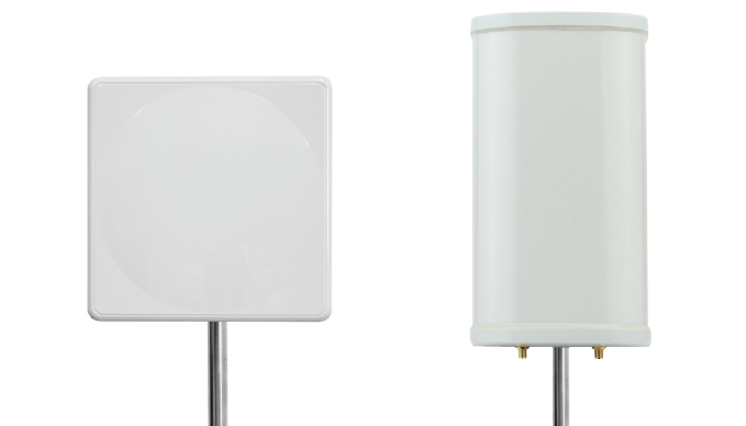
Compare the required angular coverage
| Decision | Panel antenna | Omni antenna |
|---|---|---|
| Coverage objective | A defined direction or sector | Broad azimuth coverage around the installation |
| Orientation sensitivity | Pointing and alignment can be important | Azimuth alignment may be less restrictive; elevation and platform effects remain |
| Mechanical review | Bracket, pointing adjustment, blocked sector, wind or vibration loads | Mast or vehicle mounting, ground relationship, height, and nearby structures |
| RF evidence | Azimuth and elevation cuts, polarization, sidelobes, installed sector coverage | Azimuth uniformity, elevation cuts, polarization, and platform-dependent coverage |
Omnidirectional does not mean equal radiation in every three-dimensional direction. A high-gain omni can have a restricted elevation region, so terminals above or below that region may need special attention.
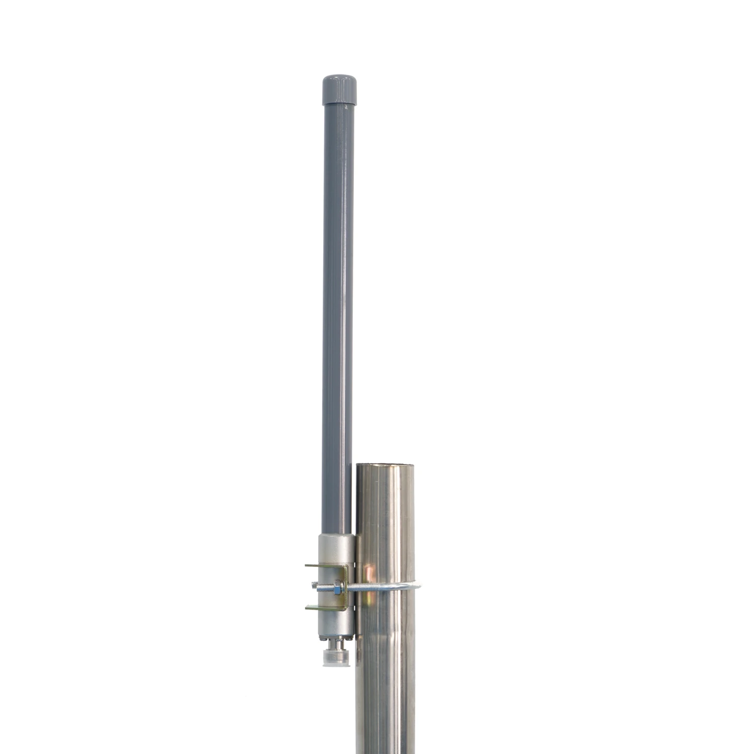
Use a link geometry before comparing gain
A fixed terminal communicating toward a known remote site may benefit from a directional panel if alignment can be maintained. A terminal serving mobile units around a site may need broad azimuth coverage. A moving platform can introduce changes in heading, roll, pitch, blockage, and height that neither catalogue pattern alone resolves.
Translate the intended geometry into coverage angles and a link budget. Include transmit power, antenna gain at the relevant angles, feed losses, receiver requirements, propagation assumptions, and margin. Compare each antenna over the required coverage region.
Check polarization and the installed structure
Specify the polarization required at both ends of the link. Review the radome, bracket, mast, vehicle surface, cables, nearby antennas, and other conductive structures. These can change the pattern or feed condition after installation.
Ask for the relevant pattern planes, frequencies, mounting state, and cable treatment. A label such as panel or omni describes a product family; measured data show how a particular configuration behaves.
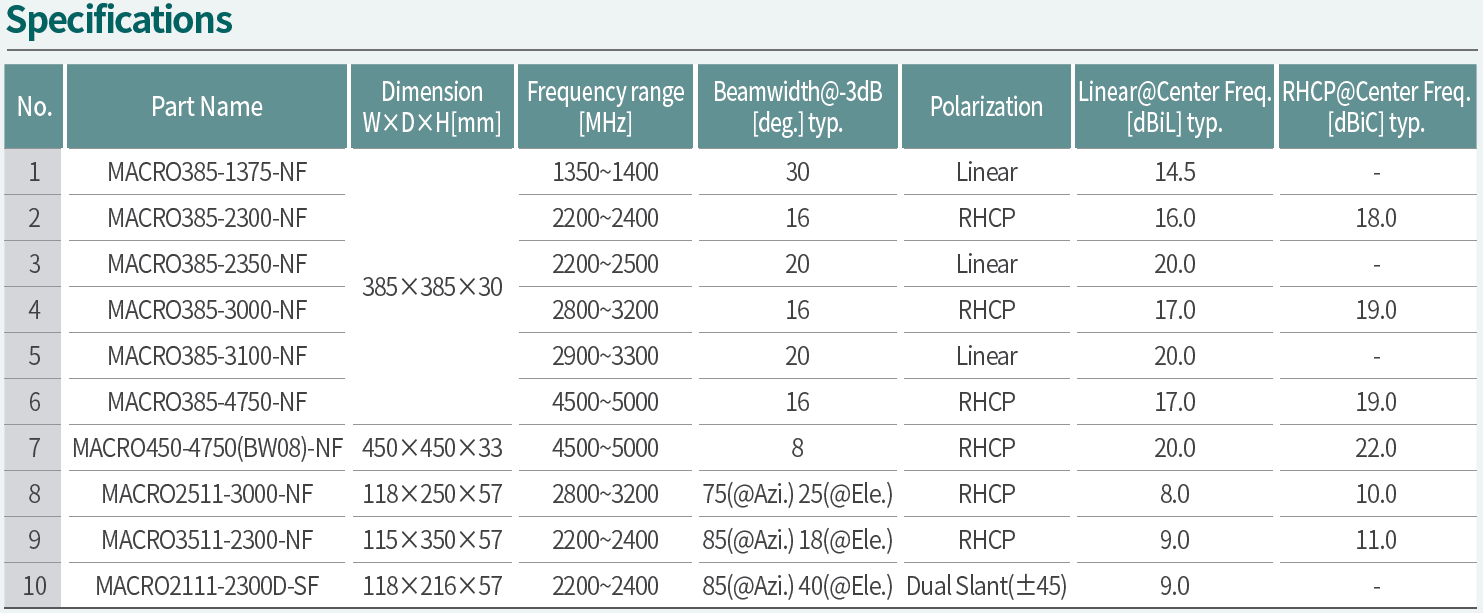
Verify the conditions that drive the choice
For a panel, test coverage across the required pointing tolerance and identify blocked directions or unwanted energy outside the sector. For an omni, examine both azimuth and elevation over the expected platform orientations. Include movement or representative orientation states where the application requires them.
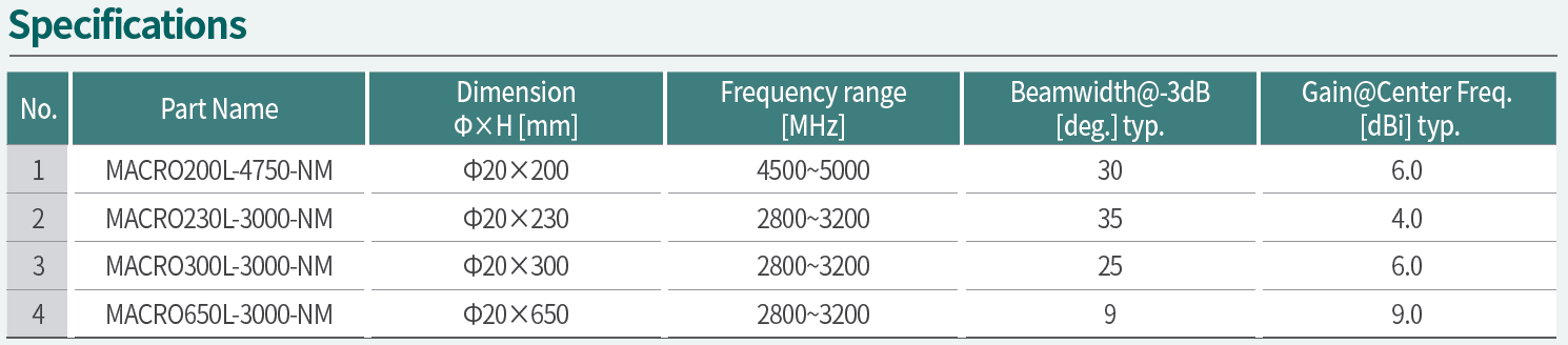
Use IEEE 149-2021 to define the antenna measurements. Select environmental tests from the platform’s life-cycle conditions and record the sample, fixture, sequence, and acceptance criteria. The test plan should connect each exposure to the RF or mechanical properties checked afterward.
Record the selected configuration
Keep the coverage sketch, antenna data, mounting drawing, polarization, feed path, link assumptions, and verification results together. Revisit the decision if the terminal geometry, platform, frequency, or mounting changes.
For a comparison with MAC technologies Inc., provide the coverage objective, platform orientation and movement, mounting surfaces, polarization, cable arrangement, and evidence required to accept the antenna choice.
References
IEEE 149-2021 Recommended Practice for Antenna Measurements
MIL-STD-810 — Environmental Engineering Considerations and Laboratory Tests
https://standards.ieee.org/ieee/149/6667/
https://quicksearch.dla.mil/qsdocdetails.aspx?ident_number=35978&lang=en