
Select RFID antennas for gate and portal systems around the path of the tagged objects. Portal dimensions, antenna placement, polarization, reader timing, cable loss, and surrounding materials affect required reads and unwanted reads in adjacent areas.
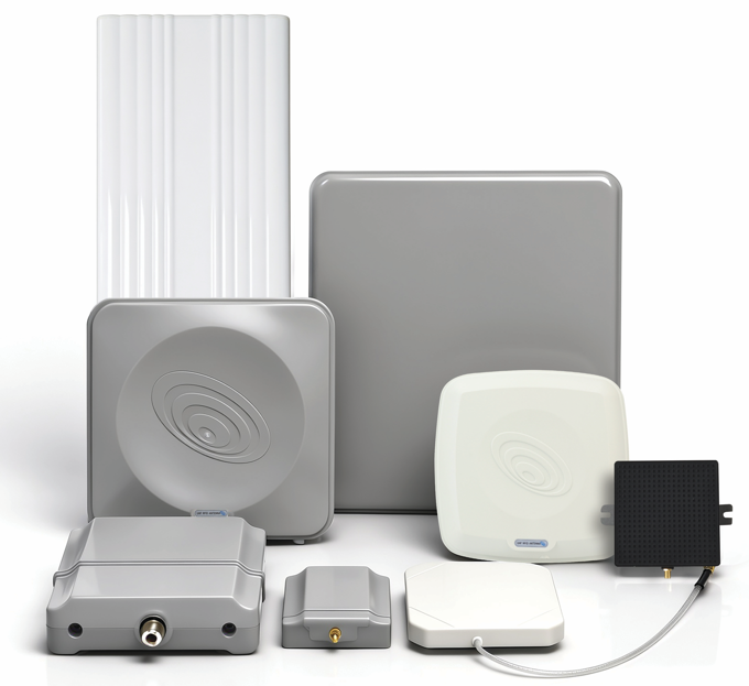
Draw the portal and its acceptance zones
| Zone | Record | Acceptance question |
|---|---|---|
| Entry | Object path, tag orientation, speed, trigger state | Is the object detected at the required stage? |
| Center | Position, active antenna port, item population | Are the required tags read during the available time? |
| Exit | Reader timing and transition to the next process | Does the transaction complete within its intended boundary? |
| Adjacent area | Waiting stock, neighboring traffic, nearby structures | Are unwanted reads controlled under realistic conditions? |
Match the antenna arrangement to the traffic
Compare antenna patterns and polarization against the angles at which tags appear. A higher peak gain may concentrate energy into a smaller angular region. Adding antennas may improve coverage, but it also changes overlap, cabling, port allocation, and the timing available to each view.
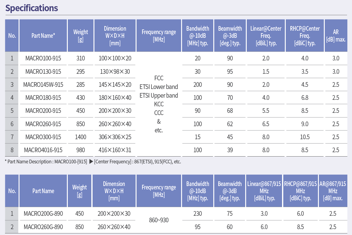
Record which antenna is connected to each reader port and how the reader schedules those ports. A change in read behavior can come from reader timing or object speed as well as from the antenna. Avoid selecting antenna count from a generic distance figure.
Commission with representative objects
Use the actual tag types, attachment materials, object sizes, orientations, and movement. Include difficult presentations and partially loaded conditions if they occur in service. Keep a run record containing the port, position, polarization, cable, power, timing, path, tag population, and result.
Test both the required route and an unwanted-read route beside the portal. If there is a second lane, run the relevant traffic condition rather than assuming separation from a static test. Define acceptance criteria before adjusting placement or power so the comparison remains meaningful.
Investigate missed and unwanted reads separately
A missed read may reflect shielding by the load, an unfavorable tag angle, insufficient time, a gap in coverage, or another system condition. An unwanted read may come from reflections, zone overlap, power settings, or application timing. Record the observation first, then change a controlled variable and repeat the same route.
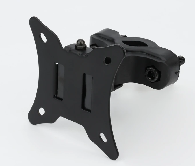
When shielding or a different bracket is introduced, retest the desired zone as well as the rejected area. An adjustment that removes an unwanted read can also create a blind region for the intended object.
Preserve the accepted configuration
Retain the portal drawing, antenna-port map, cable details, reader settings, object routes, and result records. Revisit the trial after relocation, antenna replacement, cable changes, new guards, or changes to adjacent traffic.
GS1 TIPP can help structure repeatable tagged-item tests. For European deployment, review the applicable RFID equipment and national conditions separately from operational commissioning.
For a portal review with MAC technologies Inc., share the geometry, representative traffic and tags, antenna-port plan, reader settings, and the boundaries for desired and unwanted reads.
References
GS1 TIPP
ETSI RFID technical work-program reference
https://www.gs1.org/standards/epc-rfid/tipp
https://portal.etsi.org/webapp/WorkProgram/Report_WorkItem.asp?SearchPage=TRUE&WKI_ID=62501
Related reading
Circular vs Linear Polarization in RFID Reader Antennas
RFID Antenna Application Considerations for Metal Environments