
Lightweight RFID antennas can reduce the load on a handheld reader, moving mechanism, or compact assembly. The useful comparison is the mass of the installed antenna system, including its ground structure, connector, cable, housing, and mount. A small radiator can still require a relatively large support assembly, while a larger PCB antenna may offer a better combination of mass and bandwidth for a particular reader.
The term ultra-lightweight needs a stated mass and application context. It should not be treated as a standard performance class or applied to every product in a photograph.
Compare documented mass and dimensions
The July 2026 MAC technologies Inc. catalogue provides antenna-weight and dimension fields for ceramic and PCB products. The following entries illustrate how to start a comparison using named parts rather than appearance.
| Catalogue example | Listed antenna weight | Listed dimensions W × D × H | Integration detail |
|---|---|---|---|
| Ceramic MPAC18SA915P-TA | 3 g | 18.3 × 18.3 × 2 mm | Catalogue specifies a 50 × 50 mm ground plane |
| Ceramic MPAC45SC915P-TA | 30 g | 45 × 45 × 4 mm | Catalogue specifies a 78 × 78 mm ground plane |
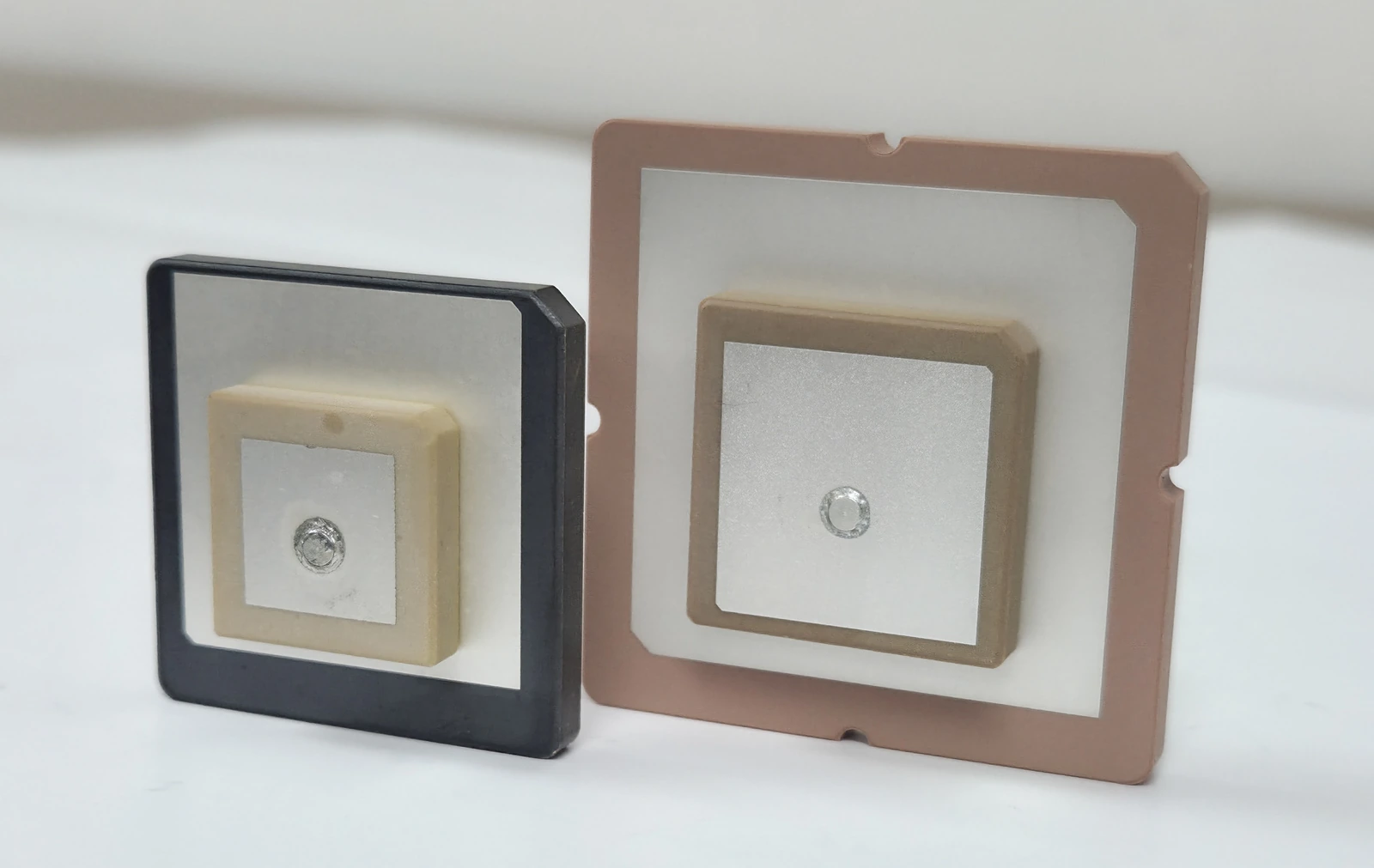
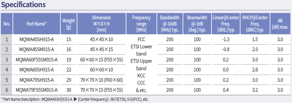
| PCB QWA MQWA45SH915-A | 15 g | 45 × 45 × 10 mm | Include the final mounting, feed, and housing in the comparison |
Source: MAC technologies Inc., July 2026 catalogue, printed pages 10–11. These are catalogue entries, not measurements of the photographed samples or guarantees for a new installation. Confirm the current drawing and what is included in the weight before procurement.
The examples show why footprint, height, ground requirements, and mass should be reviewed together. They do not establish an RF-performance ranking between the parts. A buyer should compare candidates against the same operating band, polarization, coverage, and mechanical requirements.
Separate reader antennas from tag antennas
A reader antenna connects to a powered reader and may need a ground, coaxial feed, connector, radome, and mounting hardware. Its assembly must tolerate handling and cable forces while maintaining the required read zone.
A passive tag antenna connects to a chip and is attached to an item. Conductor, substrate, chip attachment, adhesive, and protective layers affect both mass and RF behavior. The chip usually presents a frequency-dependent complex impedance, so a reader-port test cannot simply be reused as a tag acceptance test.
Flexible paper, film, foil, and textile constructions generally belong to tag design in this comparison. The cited flexible-tag study discusses material and chip-matching choices; the company catalogue examples above are rigid reader antennas.
Identify what changes when mass is reduced
| Design choice | Potential benefit | What to check |
|---|---|---|
| Thinner or smaller ceramic element | Reduced element size or mass | Required ground, bandwidth, material tolerance, and attachment stress |
| PCB construction | Defined geometry and integration with the feed | Board thickness, connector loads, ground, enclosure, and assembly mass |
| Flexible tag substrate | Conformability and low structural mass | Bend radius, conductor fatigue, adhesive, moisture, and host material |
| Reduced housing or support | Lower installed mass | Sealing, stiffness, cable restraint, handling, and service life |
Material removal can alter current paths, dielectric loading, stiffness, and durability. Matching components can compensate for some impedance changes, but their loss and tolerance also belong in the design review. Evaluate bandwidth and radiation or read-zone behavior after the mechanical design is settled.
Test the states the application will use
Measure a rigid reader antenna in its intended enclosure and mounting arrangement. Include the actual cable route and representative nearby objects. For a flexible construction, add the required bend states and attachment material; do not bend a rigid ceramic or PCB part unless its design permits it.
Keep the initial sample as a baseline, then repeat relevant RF and mechanical checks after justified temperature, moisture, handling, or flex exposure. Record whether a change exists only while loaded or remains after recovery. GS1 TIPP offers a repeatable framework for tagged-item tests, while antenna radiation measurements require an appropriate antenna-test method.
Prepare a useful weight-reduction brief
State the maximum installed mass, available volume, operating band, reader or chip interface, mounting, service conditions, and acceptance method. Identify whether cable, connector, ground, and protection are included in the target. Send those inputs to MAC technologies Inc. with the current drawing so the discussion can compare a complete assembly and the trade-offs that matter to the product.
References
MAC technologies Inc. catalogue, July 2026, printed pages 10–13. Product examples and their listed weights, dimensions and RF fields are historical catalogue data; confirm the current drawing and specification before ordering.
Flexible Radio-Frequency Identification Tag Antenna for Sensor Applications
GS1 Tagged-Item Performance Protocol
IEEE 149-2021 — IEEE Recommended Practice for Antenna Measurements
https://www.mdpi.com/1424-8220/18/12/4212
https://ref.gs1.org/guidelines/tipp/
https://standards.ieee.org/ieee/149/6667/
Related reading
RFID Antenna Design Technologies for Compact Readers
Understanding RFID Antenna Characteristics: How to Read a Datasheet