
Compact RFID reader antennas must balance size, bandwidth, efficiency, polarization, enclosure interaction, and repeatable manufacture. Select the architecture for the required read zone with the batteries, display, shielding, cables, fasteners, and housing materials included in the design.
Compact-reader work should begin with a system envelope. Define the target RFID band and region, reader output and receiver requirements, antenna location, device orientations, user grip, nearby electronics, thermal limits, and allowed tuning components. The selected antenna architecture should ultimately be verified in the production-intent PCB, enclosure, and operating environment.
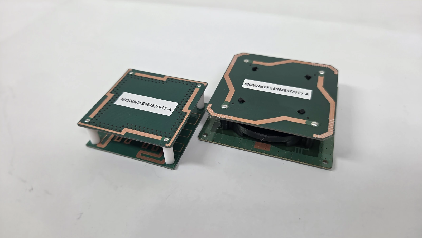
A compact reader antenna and a passive tag antenna are different design problems even when they operate in the same RFID band. A reader antenna is driven by a reader RF port and must create the required interrogation and receive zone. A passive tag antenna must collect enough incident power for its chip and return a backscattered signal, so its complex chip interface and attachment material are central to the design. Requirements, fixtures, and acceptance data should identify which side of the link is being evaluated.
Which antenna technologies fit the reader?
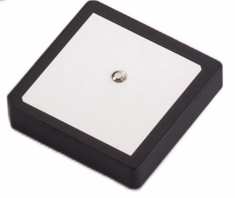
Printed monopoles, inverted-F structures, loops, patches, slots, and external antennas offer different ways to fit a reader. Their behavior depends on the available ground plane, clearance, feed position, polarization, and three-dimensional volume. Compare these constraints before choosing a topology.
A printed monopole can fit a board edge with a relatively simple feed, but its behavior depends strongly on the available ground and keep-out region. An inverted-F structure can shorten the occupied length by using a grounded branch, while feed and shorting geometry make it sensitive to the PCB, enclosure, and nearby components. A loop is often considered when magnetic coupling or a defined current path fits the application, but its inductance, resistance, tuning, and proximity loading must be measured in the final geometry.
A patch can provide a controlled broadside pattern and a ground-backed structure, but volume, substrate properties, feed method, and available ground can constrain a compact reader. A slot uses an opening in a conductive region as part of the radiator, so ground continuity, surrounding metal, and enclosure details become design inputs. An external antenna can move the radiator away from a difficult device interior and offer more installation freedom, but it introduces a connector, cable loss, routing, mounting, and configuration-control problem.
| Topology | Packaging Advantage | Integration Dependency | Main Verification Need |
|---|---|---|---|
| Printed monopole | Simple planar structure that can use a PCB edge | Ground size, clearance, feed position, housing, and nearby electronics | Installed impedance, pattern, and coverage across PCB and enclosure tolerances |
| Inverted-F or IFA-type | Folded current path can reduce occupied board length | Shorting geometry, feed point, ground plane, component keep-out, and user interaction | Sensitivity sweeps followed by production-intent assembly measurements |
| Loop | Can fit a bounded current path and support near-field-oriented implementations where appropriate | Inductance, conductor loss, tuning network, shielding, and nearby conductive material | Calibrated impedance and field or read-zone behavior in the final mechanical state |
| Patch | Ground-backed structure can support a broadside pattern and defined polarization | Substrate, ground dimensions, feed, stacked height, radome, and mounting surface | Bandwidth, polarization, pattern, and enclosure-integrated performance |
| Slot | Can share a conductive surface or ground region with the device structure | Slot geometry, ground continuity, feed coupling, cable or connector, and enclosure metal | Feed-match and installed-pattern measurements with the intended conductive structure |
| External antenna | Separates the radiator from a constrained reader interior | Connector, cable type and loss, mounting, orientation, strain relief, and user configuration | End-to-end port budget and repeatable installed read-zone acceptance |
When comparing RFID antenna design technologies for UHF passive RFID, the GS1 EPC UHF Gen2 air-interface protocol defines the interrogator-tag communication framework across 860 MHz to 930 MHz. A compact reader still needs a region-specific band and antenna implementation; protocol compliance alone says nothing about installed radiation efficiency or coverage.
Model the complete assembly
Model the dielectric materials, conductors, ground features, shields, battery, display, connectors, cable launches, housing walls, coatings, and nearby metal that affect the antenna. Sweep important tolerances, reserve tuning access, and identify variations that shift resonance or bandwidth.
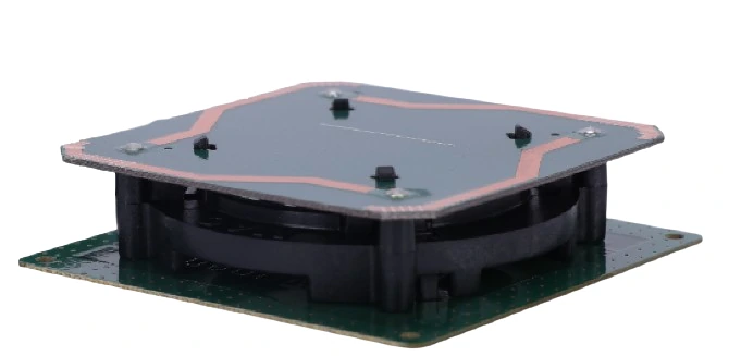
The ETSI TR 102 273-2 guidance on antenna measurement environments discusses effects from chambers, fixtures, cables, and coupling. Those considerations are especially relevant when a physically small device is measured with support hardware close to the radiator.
Use an integration and tuning workflow
Fix the system envelope before tuning the antenna geometry. Include the regional band, reader interface, ground and available volume, target polarization and read zone, enclosure, internal components, cable, and expected user grip.
Build a simulation model that includes the PCB stack, ground features, feed, enclosure, shields, batteries, displays, fasteners, and other nearby structures that materially load the antenna.
Fabricate an accessible prototype that permits calibration and controlled changes to geometry or tuning elements.
Measure that prototype on the intended PCB, then correlate the result with the model before adding further mechanical complexity.
Assemble an enclosure-integrated prototype using production-intent materials, spacing, cables, and internal components.
Tune only from measured data at the agreed reference plane, while tracking the effect on bandwidth, loss, pattern, polarization, and read-zone behavior.
Verify the installed state with representative reader settings, tags, orientations, surrounding materials, user grips, and mounting conditions.
Repeat critical measurements across samples and tolerances, then define which geometry, material, component, or process changes require revalidation.
For a passive UHF tag, the impedance objective can instead involve the frequency-dependent complex chip interface. The NXP reference label antenna application note illustrates why antenna geometry, assembly parasitics, chip impedance, and attachment conditions must be considered together. Its tag-specific procedure should not be copied as a reader-port acceptance method.
Protect manufacturability and change control
Manufacturing drawings should control copper boundaries, ground clearances, dielectric stack, tuning values, connector or spring-contact geometry, adhesive, enclosure material, and assembly spacing. Set tolerances and identify which substitutions require RF revalidation.
Production validation should track more than a single golden sample. Use a sample plan that can reveal shifts in resonance, matching, and read-zone behavior. Keep calibration files, software versions, fixtures, and raw data with the design record.
Frequently asked questions
Does a smaller antenna always reduce performance? Not always, but miniaturization commonly tightens bandwidth, efficiency, tolerance, or integration trade-offs. The final assembly must be measured.
Can simulation replace a prototype? No. It is valuable for design choices and sensitivity analysis, but material properties and assembly details require physical correlation.
What is the earliest useful test? Measure the feed match on a production-like PCB, then repeat after each major enclosure or electronics integration step.
Continue with RF technology insights, RF antenna and component resources, and the applications hub.
Discuss compact reader antenna integration requirements.
References
NXP AN1715 — Reference Label Antenna Design for PCB Applications, Rev. 3.0 (tag-side design reference).
https://www.nxp.com/docs/en/application-note/AN171530.pdf
GS1 EPC UHF Gen2 Air Interface Protocol
ETSI TR 102 273-2 V1.2.1
IEEE 149-2021 — IEEE Recommended Practice for Antenna Measurements
https://www.gs1.org/standards/rfid/uhf-air-interface-protocol
https://www.etsi.org/deliver/etsi_tr/102200_102299/10227302/01.02.01_60/tr_10227302v010201p.pdf
https://standards.ieee.org/ieee/149/6667/
Related reading
Why Lightweight and Ultra-Lightweight RFID Antennas Matter