
Choose an RFID reader antenna manufacturer by how well its products and engineering support fit the installed application. Define the operating band, reader interface, cable, polarization, mounting geometry, read zone, environment, and acceptance tests before comparing suppliers. This gives every candidate the same requirement and makes the comparison useful beyond a headline gain figure.
That distinction matters because a reader antenna is part of a coupled RF system. The enclosure, mounting surface, cable loss, connector, nearby metal, reader power, tag orientation, and tagged material can all change the field delivered to the application. Supplier evaluation should therefore be based on project-specific requirements, comparable evidence, and validation under the intended installation conditions.
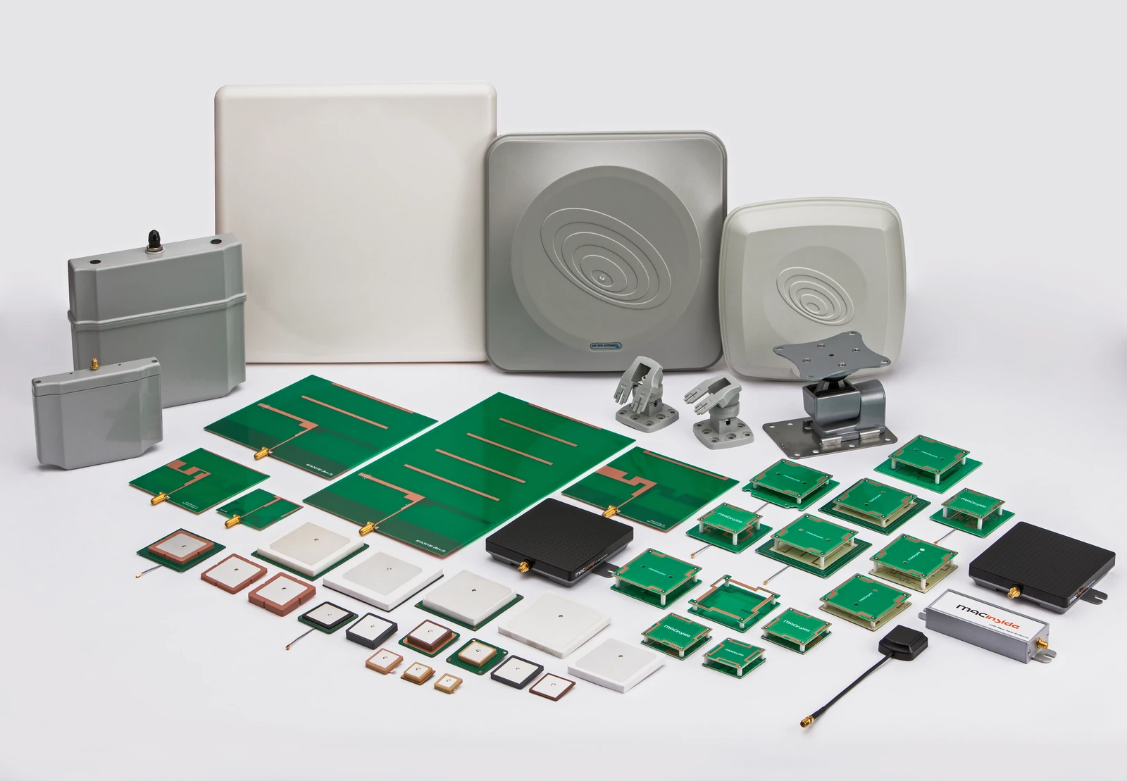
What should the antenna requirement brief contain?
Start with the workflow and geometry. Record where tags move or remain stationary, the permitted antenna locations, minimum and maximum distance, expected tag orientations, nearby materials, and zones where reads must not occur. Then add the electrical and mechanical interfaces.
regional frequency band and reader port impedance
connector, cable type, maximum cable length, and reference plane
required polarization, coverage shape, and mounting orientation
available volume, fasteners, grounding, sealing, and temperature range
measurable read-zone criteria using representative tagged items
| Requirement Area | Buyer Must Define | Evidence to Request | Validation Point |
|---|---|---|---|
| Band | Deployment country, operating band, and reader configuration | Supported frequency range and the conditions attached to it | Confirm the production-intent antenna and reader configuration in the target market |
| Reader-to-antenna interface | Reader manufacturer or integrator defines port impedance, connector, cable, maximum length, and reference plane | Antenna supplier provides interface drawings, cable data, and antenna measurement setup | Integrator verifies the assembled reader, cable, and antenna from the agreed reference plane |
| Polarization and read zone | Tag orientations, desired coverage, exclusion zones, and mounting angle | Polarization information and pattern data with frequency and coordinates | Exercise representative tags throughout desired and unwanted zones |
| Mechanical integration | Envelope, fasteners, grounding, nearby materials, and keep-out areas | Revision-controlled drawings and installation limits | Repeat RF checks in the production-intent enclosure and mounting state |
| Environment | Temperature, moisture, ingress, cleaning, vibration, or other justified exposures | Applicable material data and attributable test records | Recheck relevant RF and mechanical properties after tailored exposure |
| Change control | Characteristics that may affect tuning, pattern, or installation | Controlled bill of materials, revision history, and notification process | Define which material, cable, enclosure, or process changes trigger revalidation |
For passive UHF systems, the GS1 EPC UHF Gen2 air-interface specification defines communication between interrogators and tags in the 860 MHz to 930 MHz range. It does not select an antenna or guarantee performance in a particular installation, so the procurement specification still needs regional and system-level limits. The reader manufacturer or integrator defines protocol operation and system limits; the antenna supplier provides the component specifications needed to evaluate that configuration.
Compare evidence at the same reference conditions
Ask each candidate to identify whether values are minimum, typical, simulated, or measured. A gain number is not comparable unless frequency, polarization, coordinate system, cable treatment, fixture, and uncertainty are known. Likewise, return loss or VSWR should identify the measurement reference plane and the installed configuration.
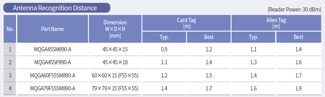
IEEE 149-2021 describes recommended methods for measuring antenna properties, including radiation patterns. Ask the supplier which method, fixture, calibration, and configuration were used for the data being reviewed.
Review integration and change control
Identify who controls the antenna drawing, cable assembly, connector selection, mounting bracket, tuning state, and acceptance record. Request revision-controlled dimensions and define which changes require revalidation. A material substitution, cable change, altered mounting gap, or enclosure coating can affect RF behavior.
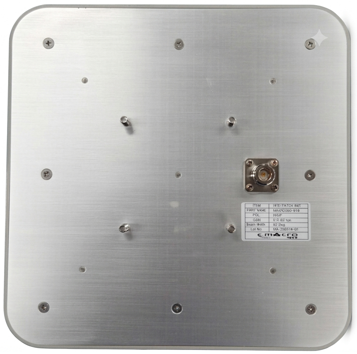
The reader manufacturer or integrator should lead installed-system prototype testing with production-intent parts and record reader configuration, tagged items, orientation, distance, surroundings, and pass/fail criteria. The antenna supplier provides antenna specifications, gain, radiation-pattern, polarization, frequency-response, and interface data for that review. If the finished product is radio equipment placed on the European market, the European Commission overview of the Radio Equipment Directive explains the essential requirements for safety, electromagnetic compatibility, and efficient spectrum use. The manufacturer placing that finished radio equipment on the market remains responsible for its applicable conformity assessment and technical documentation.
The European Commission RED Guide distinguishes a passive antenna sold as a standalone commercial unit from an active antenna containing electronics that interact with the RF signal. The former is outside the RED scope described in that guidance; active antennas are covered. This is not an exemption from every applicable rule. Assess the actual product, supplied configuration, intended use, and market before assigning compliance tasks.
Build a decision record buyers can audit
Compare candidates on requirement coverage, evidence quality, unresolved integration risks, test readiness, and ownership of corrective action. Record each exception and the test or document needed to resolve it before supplier selection.
| Evaluation Area | Evidence Available | Open Risk | Buyer Decision |
|---|---|---|---|
| Requirement coverage | Identify the controlled document and revision reviewed | List every exception, ambiguity, or unsupported value | Accept, reject, or request a clarified response |
| RF evidence | Record whether data are simulated, measured, typical, or guaranteed | Note missing conditions, fixtures, uncertainty, or installed-state evidence | Define the comparison or verification still required |
| Integration readiness | Reference antenna supplier drawings, interface data, and production-intent antenna samples | Record enclosure, cable, mounting, or tagged-item dependencies | Approve the next prototype stage only when dependencies are controlled |
| Change control | Reference the proposed material, process, and notification controls | Identify substitutions that could alter RF or mechanical behavior | State which changes require notification, approval, and retest |
| Corrective-action ownership | Name the party responsible for each open item | Record schedule and acceptance impact without assuming closure | Assign an owner, evidence deliverable, and decision date |
Before issuing an RFQ, confirm that the buyer has:
defined the deployment region, reader interface, tagged items, read zone, and exclusion zones;
issued controlled mechanical and environmental constraints;
stated which values require measured rather than simulated evidence;
defined the installed acceptance setup, sample configuration, and pass/fail rules;
identified design-file, tooling, change-notification, and revalidation responsibilities; and
separated verified evidence from supplier statements that remain pending review.
Frequently asked questions
Can a datasheet identify the best RFID reader antenna manufacturer? No. It can establish candidate values, but selection requires comparable conditions, attributable evidence, and installed-system validation.
Should the highest-gain antenna win? Not automatically. Beam shape, polarization, cable loss, unwanted reads, mounting constraints, and regional limits can matter more than a single peak value.
What evidence should accompany a supplier proposal? Request the relevant drawings, specifications, test conditions, delivery scope, and applicable certificates. Each document should identify the product or activity it covers.
For adjacent planning topics, see RF technology insights, RF antenna and component resources, and the applications hub.
Request an application review for an RFID reader antenna.
References
GS1 EPC UHF Gen2 Air Interface Protocol
IEEE 149-2021 — IEEE Recommended Practice for Antenna Measurements
European Commission — Radio Equipment Directive
https://www.gs1.org/standards/rfid/uhf-air-interface-protocol
https://standards.ieee.org/ieee/149/6667/
European Commission RED Guide — antenna scope, section 1.6.3.4; Directive 2014/53/EU — manufacturer obligations, Article 10
https://eur-lex.europa.eu/legal-content/EN/TXT/PDF/?uri=CELEX%3A02014L0053-20221227
Related reading
RFID Antenna Specifications: A Selection Guide
OEM vs ODM Antenna Manufacturing: Scope, Process, and Deliverables