
Custom mounting guides connect an antenna design to a repeatable installation. They should define more than a bracket shape: the guide must control the mounting surface, orientation, clearances, fasteners, cable route, connector strain, environment, and RF validation state. A mechanically secure installation can still be electrically different from the configuration used during development.
Document the installation environment
Document where the antenna will be installed and what surrounds it. Identify the mounting-surface material and thickness, ground-plane relationship, nearby metal, enclosure or radome, equipment behind the surface, user access, and allowable keep-out area. Photographs are useful, but controlled dimensions and material descriptions are needed for repeatability.
Define the permitted orientation and any directional reference. For RFID systems, this may include reader-antenna polarization, tag orientation, read-zone boundary, height, and nearby reflecting structures. For communication antennas, the platform and cable route may influence pattern, tuning, and link behavior.
Specify the mechanical interface
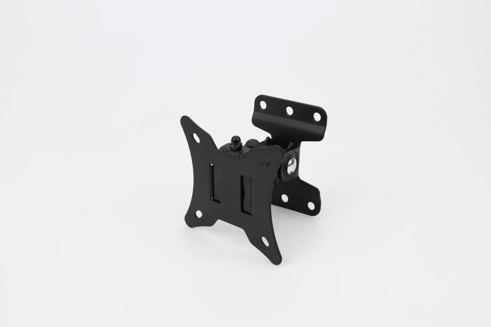
The installation drawing should show hole pattern, bracket geometry, interface datums, fastener type, washer or locking method, torque guidance where applicable, tolerances, and service access. State bracket and mounting-surface materials because conductive parts can influence the antenna.

Avoid leaving installers to infer the antenna origin or pointing direction from appearance. Use clear orientation marks and a defined coordinate reference. If more than one bracket or mounting state is approved, identify each configuration and the corresponding validation evidence.
| Installation item | Guide content | Verification method |
|---|---|---|
| Mounting surface | material, thickness, ground relationship | drawing and site inspection |
| Bracket and fasteners | geometry, material, torque or retention | mechanical inspection |
| Clearance | keep-out zone and nearby conductive objects | dimensional check |
| Cable | type, route, bend radius, strain relief | installation inspection and RF check |
Control ground plane, metal proximity, and clearance
Nearby conductive structures can change current distribution, impedance, and radiation pattern. A mounting guide should identify minimum clearances and surfaces that form part of the intended ground. Do not assume that moving the antenna a small mechanical distance is electrically insignificant.
If installation conditions vary across platforms, define a bounded range or require a platform-specific review. A generic instruction such as “keep away from metal” is rarely sufficient; the guide should show the relevant zone and the exception process when the site cannot meet it.
Route the cable as part of the antenna system
Cable type, length, exit direction, bend radius, attachment points, and proximity to the radiator can affect both RF behavior and durability. Specify connector mating, strain relief, drip loop or sealing approach where relevant, and the route that was used during validation. Prevent cable weight or vibration from loading the connector.
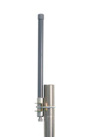
Serviceability also matters. An installer should be able to connect, inspect, and replace the assembly without introducing an unapproved route or orientation. If excess cable is permitted, state where it may be secured and how tightly it may be coiled.
Address the operating environment
The guide should identify the environmental assumptions supplied by the project: indoor or outdoor location, temperature range, moisture or wash-down exposure, vibration, shock, UV exposure, corrosion concerns, and cleaning materials. These conditions inform fasteners, sealing, materials, and inspection, but they should not be converted into unsupported product ratings.
When an environmental qualification is required, link the installed configuration to the applicable test plan. The bracket, fasteners, cable, connector, and enclosure state used for testing should match the controlled installation definition.
Revalidate RF behavior after installation
Bench tuning is not final evidence when the mounting state changes the electromagnetic environment. Verify the intended bracket, ground, cable, enclosure, orientation, and representative nearby objects. IEEE Standard 149 offers antenna measurement-practice context; the project must still define its own installed configuration and acceptance criteria.
Choose the validation method that answers the system question. This may combine a feed measurement with pattern, gain, efficiency, read-zone, or link testing. Record reader power, tag type and orientation for RFID work, or radio and link conditions for a communication system. Do not use an acceptable return-loss result as the sole proof of installed performance.
Make the installation inspectable
Give installers a drawing and checklist covering part identification, approved configuration, tools, fasteners, sequence, orientation, clearances, cable routing, connector checks, sealing and inspection. Include a defined process for sites that cannot meet the approved conditions.
For custom mounting guides with MAC technologies Inc., provide the platform drawing, mounting materials, ground relationship, bracket constraints, cable and connector state, environmental assumptions, service requirements, and installed RF verification method. See the applications hub and RF technology insights for related design considerations.
References
IEEE Standard 149
https://standards.ieee.org/ieee/149/6667/
Related reading
RFID Antenna Mounting Guide for Industrial Installations