
An industrial RFID antenna mounting guide should let an installer reproduce the orientation, clearance, and cable arrangement that were accepted during testing. Mechanical security and RF performance must be checked together: a firmly attached antenna can still behave differently after its ground relationship, cable route, or nearby structures change.
Confirm the mounting location before drilling
Identify the surface material and thickness, mounting height, required pointing direction, available clearance, nearby machinery, and access for service. Check whether the antenna design depends on a ground plane or a particular spacing from metal. Use the approved product drawing for hole patterns, loads, and any specified fastener or torque values.
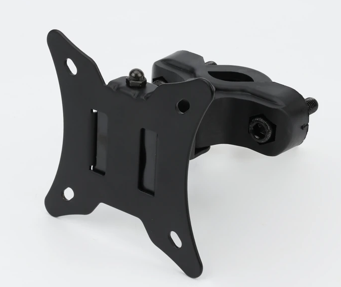
Check the bracket plate, pole or wall attachment, adjustment range, and connector access against the selected antenna drawing. Use the product-specific compatibility information when comparing mounting options.
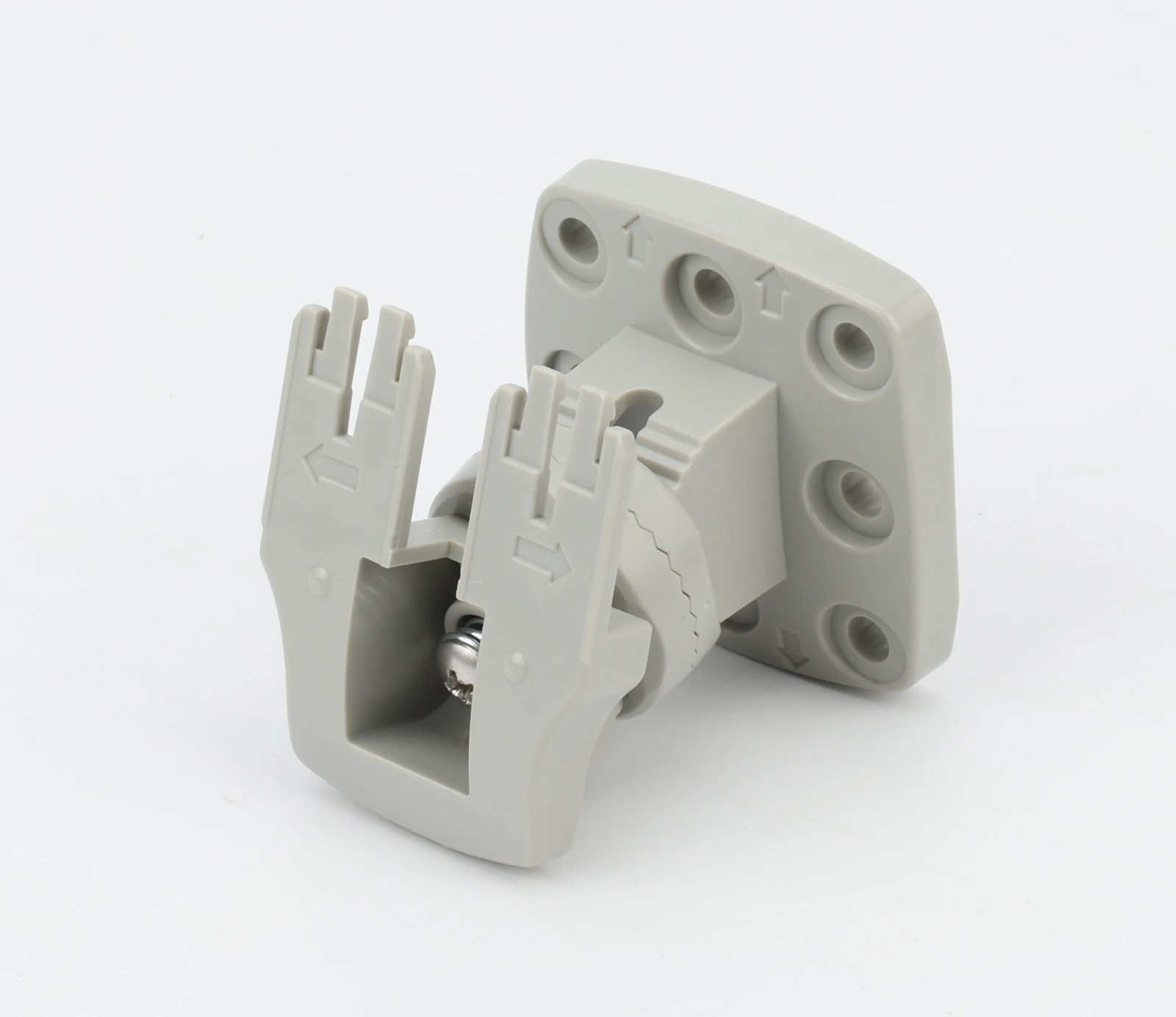
Install in a controlled sequence
1. Confirm the antenna, bracket, drawing revision, and installation location.
2. Position the bracket and check orientation, clearance, fastener access, and service space.
3. Fit the antenna using the approved fastening and retention method.
4. Route and secure the cable, preserving bend radius and protecting the connector from cable weight or vibration.
5. Complete sealing or connector protection required by the released installation instructions.
6. Inspect the as-built arrangement and run the agreed read-zone test.
Do not substitute a fastener, spacer, bracket material, or cable route without checking its mechanical and RF consequences. Where the documentation provides no value, request the applicable specification rather than inventing a universal installation rule.
Keep the mechanical and RF records connected
| Installation item | Record | Verification |
|---|---|---|
| Position and orientation | Drawing reference, mounting height, pointing direction | Compare the installed assembly with the drawing |
| Clearance | Nominal value, tolerance, nearest structures | Measure in operating and relevant service states |
| Cable | Type, length, route, restraint, connector | Inspect the feed path and strain relief |
| Protection | Enclosure, seals, cleaning exposure | Check the approved installation details |
| Read zone | Reader settings, tags, route, accepted and rejected areas | Repeat the commissioning trial |
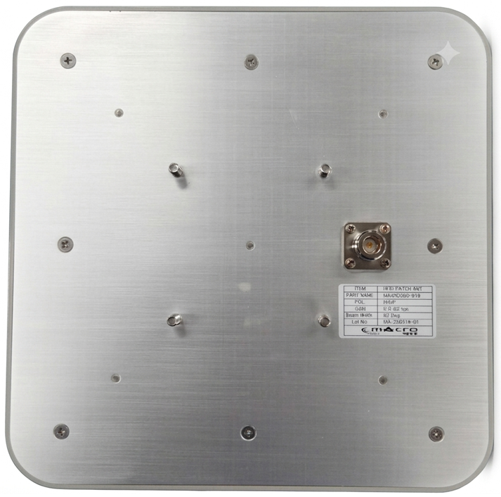
Commission after the final assembly is fitted
Use the intended reader configuration and representative tagged objects. Test the required orientations, movement, and surrounding loads, including locations where reads must not occur. If the system depends on a metal tray, guard, door, or conveyor, place it in the operational state during the trial.
A feed measurement can help detect a change in antenna loading or connection. It does not replace a read-zone test. Keep the physical inspection and the system results as separate observations tied to the same installation revision.
Make maintenance repeatable
Keep a photograph of the accepted orientation with the controlling drawing and cable plan. Specify what repeats after the antenna is moved, a bracket is adjusted, or the cable is replaced. A short change record should identify the changed item, reason, approved configuration, and RF check performed.
For an installation review with MAC technologies Inc., provide the mounting drawing, surface and bracket details, cable arrangement, environmental conditions, and commissioning criteria. A custom guide can then address the actual site and the technician's work sequence.
References
GS1 TIPP
IEEE 149-2021 Recommended Practice for Antenna Measurements
https://www.gs1.org/standards/epc-rfid/tipp
https://standards.ieee.org/ieee/149/6667/
Related reading
RFID Antennas for Gate and Portal Systems
A Guide to Requesting a Custom RFID Antenna Design
Custom Mounting Guides for Antenna Installation Environments